Ransburg, Vector r series classic applicators - maintenance, Attaching barrel to handle – Ransburg Vector R Series Classic 79520 R90 Waterborne User Manual
Page 44
Vector R Series Classic Applicators - Maintenance
40
Ransburg
AH-06-02.12
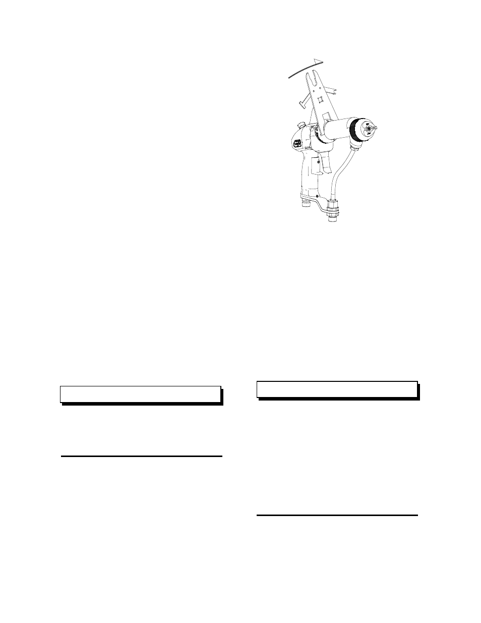
Attaching Barrel to Handle
1. If the barrel retaining nut has been removed,
it will have to be reinstalled before the barrel can
be attached to the handle.
2. Place the retaining nut over the rear of the
barrel and slide it as far forward as possible.
3. Spread the retaining ring and place it onto the
barrel. Starting at one end, lift the retaining ring
over the captive ridge and spiral into place.
4. Place the large hole of the gasket over the nee-
dle shaft and onto the base of the barrel packing
chamber.
5. While holding the barrel with the air nozzle
pointing downward, install the needle shaft spring
into the spring retainer. Align the rear end of
the barrel assembly with the matting area of the
handle assembly, and the needle shaft spring with
the spring recess in the handle. Slide the barrel
into the handle cavity until it is seated against
the gasket. Ensure the needle shaft spring seats
properly into the handle recess.
6. While holding the barrel in place, screw the
retaining nut onto the handle by hand and then
tighten using the special multi-purpose wrench.
Torque the retaining ring to 8-10 lbs•ft
or after hand tightening, torque an ad-
ditional 1/6 to 1/8 turn using the special
multi-purpose wrench.
NOTE
7. Check the spacing between the back of the
spring retainer and the handle. It should be about
1/8 inch. If not, check for one or more of the fol-
lowing:
• Gasket has been left out
• Loose retaining nut
• Loose fluid nozzle
• Improper adjustment of the trigger adjustment
nut and spring retainer
8. Secure the trigger with the two (2) shoulder
screws.
Figure 20: Barrel to Handle Assembly
The needle shaft travel
MUST be
checked. The air valve stem must be
engaged and moved back slightly before
the trigger engages the trigger adjustment
nut. If this does not occur then the trig-
ger adjustment nut and/or the trigger set
screw must be adjusted. The 11/16 inch
dimension is only a starting place for trig-
ger adjustment and can be altered to ob-
tain proper triggering sequence.
NOTE
C W