Display, Keyboard/display interface electronics, Keypad decoder – Teledyne GFC-7001E - Trace CO Analyzer User Manual
Page 253: 2 x 40 char. vacuum fluorescent display, C interface
Theory of Operation
Model GFC7001E Carbon Dioxide Analyzer
Teledyne Analytical Instruments
253
11.5.10.3. Display
The main display of the analyzer is a vacuum florescent display with two lines of 40 text characters each.
Information is organized in the following manner (see Figure 11-17):
Mode Field: Displays the name of the analyzer’s current operating mode.
Message Field: Displays a variety of informational messages such as warning messages, operation data
and response messages during interactive tasks.
Concentration Field: Displays the actual concentration of the sample gas currently being measured by
the analyzer.
Keypad Definition Field: Displays the definitions for the row of keys just below the display. These
definitions are dynamic, context sensitive and software driven.
11.5.10.4. Keyboard/Display Interface Electronics
FRONT PANEL
Keypad
Decoder
Key Press
Detect
KEYBOARD
Beeper
Sample LED
(Green)
Cal LED
(Yellow)
Fault LED
(Red)
Display Data
Decoder
Display Power
Watchdog
From 5 VDC
Power Supply
I
2
C to Relay Board
Pa
ra
lle
l D
ata
2 x 40 CHAR. VACUUM
FLUORESCENT DISPLAY
Display
Controller
D
isp
la
y W
rit
e
Clo
ck
Serial
Data
I
2
C
to
/fr
o
m C
P
U
Ke
yb
o
ard In
te
rru
pt
S
tat
us
Bi
t
I
2
C Interface
2
nd
Lang.
Switch
Maint.
Switch
Optional
Maintenance
LED
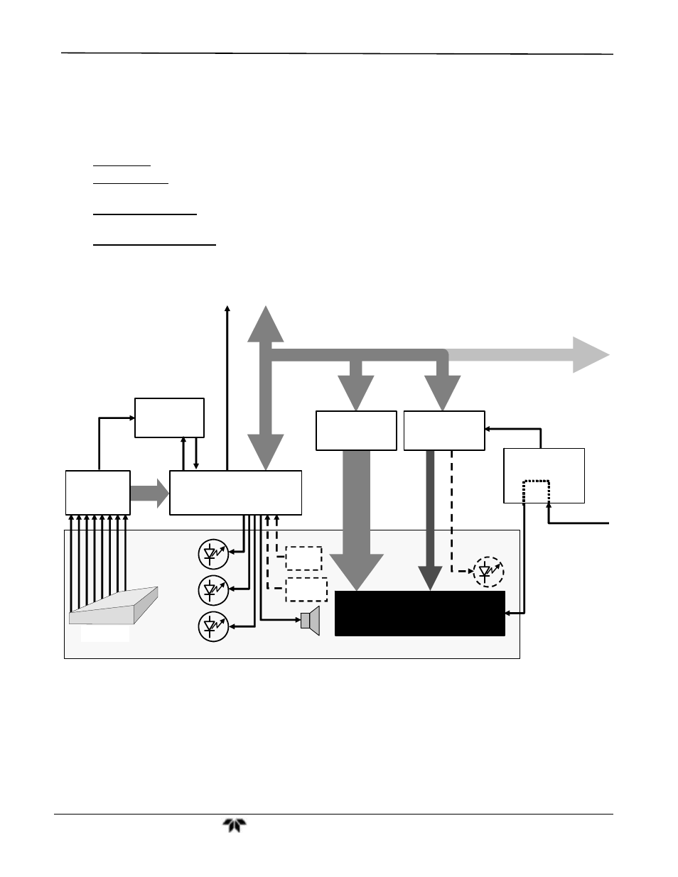
Figure 11-18: Keyboard and Display Interface Block Diagram
The keyboard/display interface electronics of the GFC 7001E/EM Analyzer watches the status of the eight front
panel keys, alerts the CPU when keys are depressed, translates data from parallel to serial and back and
manages communications between the keyboard, the CPU and the front panel display. Except for the Keyboard
interrupt status bit, all communication between the CPU and the keyboard/display is handled by way of the
instrument’s I
2
C bus. The CPU controls the clock signal and determines when the various devices on the bus
are allowed to talk or required to listen. Data packets are labeled with addresses that identify for which device
the information is intended.