Teledyne GFC-7001E - Trace CO Analyzer User Manual
Page 127
Advanced Features
Model GFC7001E Carbon Dioxide Analyzer
Teledyne Analytical Instruments
127
7.3. SETUP MORE DIAG: USING THE DIAGNOSTICS
FUNCTIONS
A series of diagnostic tools is grouped together under the SETUPMOREDIAG menu, as these parameters
are dependent on firmware revision (see Appendix A). These tools can be used in a variety of troubleshooting
and diagnostic procedures and are referred to in many places of the maintenance and trouble-shooting sections
of this manual.
The various operating modes available under the DIAG menu are:
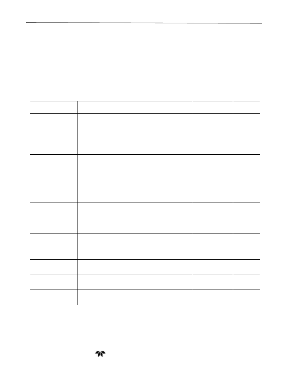
Table 7-5: Diagnostic Mode (DIAG) Functions
DIAG SUBMENU
SUBMENU FUNCTION
Front Panel Mode
Indicator
MANUAL
SECTION
SIGNAL I/O
Allows observation of all digital and analog signals in
the instrument. Allows certain digital signals such as
valves and heaters to be toggled ON and OFF.
DIAG I/O
13.1.3
ANALOG OUTPUT
When entered, the analyzer performs an analog
output step test. This can be used to calibrate a
chart recorder or to test the analog output accuracy.
DIAG AOUT
13.5.7.1
ANALOG I/O
CONFIGURATION
This submenu allows the user to configure the
analyzer’s analog output channels, including
choosing what parameter will be output on each
channel. Instructions that appear here allow
adjustment and calibration of the voltage signals
associated with each output as well as calibration of
the analog to digital converter circuitry on the
motherboard.
DIAG AIO
7.4.1
ELECTRICAL
TEST
When activated, the analyzer performs an electrical
test, which generates a voltage intended to simulate
the measure and reference outputs of the
SYNC/DEMOD board to verify the signal handling
and conditioning of these signals.
DIAG ELEC
9.6.4
13.5.6.2
DARK
CALIBRATION
1
Disconnects the preamp from synchronous
demodulation circuitry on the SYNC/DEMOD PCA to
establish the dark offset values for the measure and
reference channel.
DIAG DARK
CAL
9.6.1
PRESSURE
CALIBRATION
1
Allows the user to calibrate the sample pressure
sensor.
DIAG PCAL
9.6.2
FLOW
CALIBRATION
1
This function is used to calibrate the gas flow output
signals of sample gas and ozone supply.
DIAG FCAL
9.6.3
TEST CHAN
OUTPUT
Selects one of the available test channel signals to
output over the A4 analog output channel.
DIAG TCHN
7.4.6
1
These settings are retained after exiting DIAG mode.