Teledyne GFC-7001E - Trace CO Analyzer User Manual
Page 244
Theory of Operation
Model GFC7001E Carbon Dioxide Analyzer
Teledyne Analytical Instruments
244
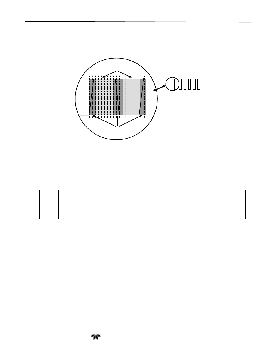
Timing for activating the Sample and Hold Circuits is provided by a Phase Lock Loop (PLL) circuit. Using the
segment sensor output as a reference signal the PLL generates clock signal at ten times that frequency. This
faster clock signal is used by the PLD to make the Sample and Hold Circuits capture the signal during the center
portions of the detected waveform, ignore the rising and falling edges of the detector signal.
Sample & Hold
Active
Detector
Output
Sample & Hold
Inactive
Figure 11-13: Sample & Hold Timing
11.5.4.3. Sync/Demod Status LED’s
The following two status LED’s located on the sync/demod board provide additional diagnostic tools for checking
the GFC Wheel rotation.
Table 11-3: Sync/Demod Status LED Activity
LED
Function
Status OK
Fault Status
D1
M/R Sensor Status
LED flashes approximately
2/second
LED is stuck
ON or OFF
D2
Segment Sensor
Status
LED flashes approximately
6/second
LED is stuck
ON or OFF
See Section 13.1.4.2 for more information.
11.5.4.4. Photo-Detector Temperature Control
The sync/demod board also contains circuitry that controls the IR photo-detector’s Thermal Electric Coolers
(TEC). A drive voltage, PHT DRIVE, is supplied to the coolers by the sync/demod board which is adjusted by the
sync/demod board based on a return signal called TEC control which alerts the sync/demod board of the
detector’s temperature. The warmer the detector, the harder the coolers are driven.
PHT DRIVE is one of the Test Functions viewable by the user via the form panel. Press
appears on the display.
11.5.4.5. Dark Calibration Switch
This switch initiates the Dark Calibration procedure. When initiated by the user (See Section 9.6.1 for more
details), the dark calibration process opens this switch, interrupting the signal from the IR photo-detector. This
allows the analyzer to measure any offset caused by the sync/demod board circuitry.