Teledyne GFC-7001E - Trace CO Analyzer User Manual
Page 241
Theory of Operation
Model GFC7001E Carbon Dioxide Analyzer
Teledyne Analytical Instruments
241
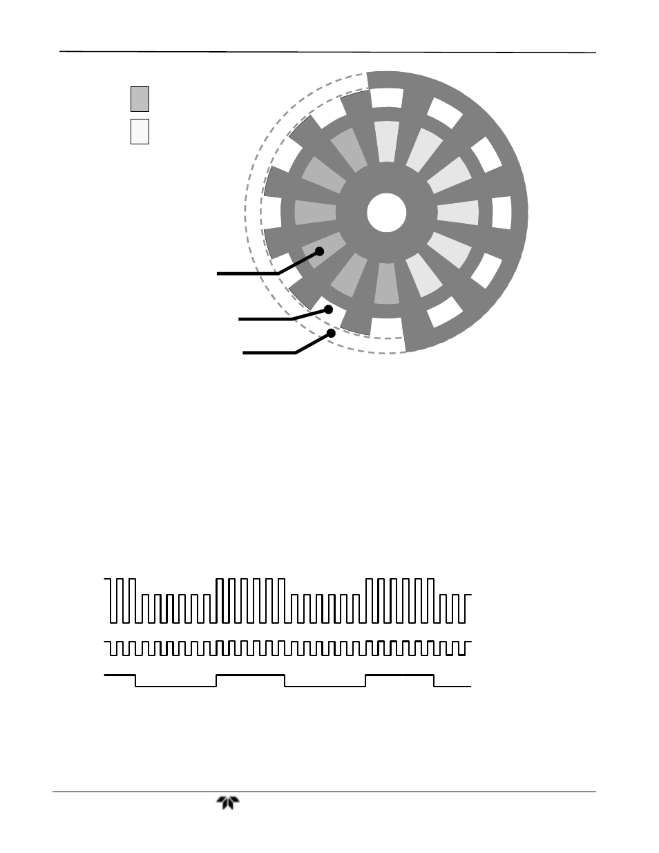
IR Detection Ring
Segment Sensor Ring
M/R Sensor Ring
KEY:
Detection Beam shining
through MEASUREMENT
side of GFC Wheel
Detection Beam shining
through REFERENCE side
of GFC Wheel
Figure 11-10: GFC Light Mask
M/R SENSOR
This emitter/detector assembly produces a signal that shines through a portion of the mask that allows light to
pass for half of a full revolution of the wheel. The resulting light signal tells the analyzer whether the IR beam is
shining through the measurement or the reference side of the GFC Wheel.
SEGMENT SENSOR
Light from this emitter/detector pair shines through a portion of the mask that is divided into the same number of
segments as the IR detector ring. It is used by the synchronous/demodulation circuitry of the analyzer to latch
onto the most stable part of each measurement and reference IR pulse.
Reference
Pulses
Measurement
Pulses
IR Beam
Pulses
Segment Sensor
Pulses
MR Sensor
Pulses
Figure 11-11: Segment Sensor and M/R Sensor Output
SCHMIDT TRIGGERS
To ensure that the waveforms produced by the Segment Sensor and the M/R Sensor are properly shaped and
clean, these signals are passed through a set of Schmidt Triggers circuits.