Figure 4-9. fnc function block, a input selected – Micromod Micro-DCI: 53HC2600 LoopMaster SL6000 CONFIGURATION TOOLKIT User Manual
Page 48
53HC2600 INSTRUCTION MANUAL
40 Online Configurations
1.
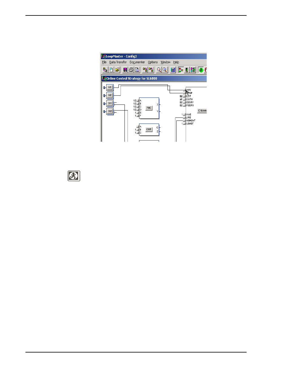
Click on the C Scheme A input button as shown in
2.
The Input Selection dialog shows the currently selected source as Analog Input AI1. To
change the PV input to come from FNC:
a.
In the Input Selection dialog, click on the down arrow button to view the list of possible
sources.
b.
Select FNC Output X.
c.
Click OK. The connection is now drawn from the FNC X output to the C Scheme A input
and the controller stops.
3.
There are four analog inputs and two digital inputs to the FNC block. To connect AI1 to FNC
input A:
a.
Click on the FNC A input button which is on the left of the FNC block next to input A.
b.
In the Input Selection dialog for FNC Input A, click on the down arrow to drop down the list.
c.
Click on Analog Input AI1, then click OK. A connection is drawn from AI1 to FNC input A,
as illustrated in
.
Figure 4-9. FNC Function Block, A Input Selected
✎ NOTE
Altering function block connections causes the controller to stop. In
the stop state, all of the controller outputs are held where they were
when the stop state was entered. To resume control action, click on
the toolbar Run button.