Optical – Luminex 100 User Manual Version 1.7 User Manual
Page 33
x
MAP Technology
System Overview
PN 89-00002-00-063 Rev. A
3 - 9
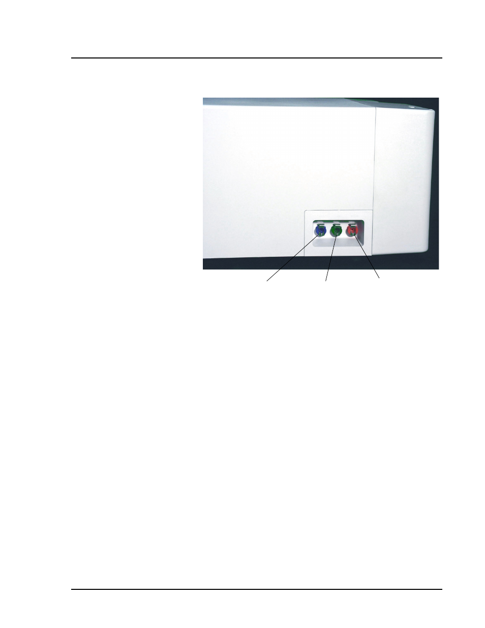
Figure 3-7. Left Side of Analyzer - Air and Fluid Connectors
Sheath fluid container (not shown): Holds sheath fluid. For
proper operation, place the container at the same level as the
analyzer. Do not place the container on top of the Luminex 100
analyzer.
The sheath fluid level should be below the air inlet connection and
above the sheath outlet connection. Sheath fluid levels must be
monitored manually. Check the sheath fluid level before starting a
run or procedure.
Waste fluid container (not shown): Receives waste from the
system. Monitor the waste fluid levels—do not allow the waste
container to overflow! Empty the waste container each time you fill
the sheath fluid container. Do not put the waste container on top of
the Luminex 100 analyzer.
Optical
The optical system contains the optics assembly and the excitation
lasers. The optical assemblies do not require user adjustment.
Sheath Fluid
Connector (Blue)
Waste
Connector
(Orange)
Air Connector
(Green)