Luminex 100 analyzer overview, Electronic – Luminex 100 User Manual Version 1.7 User Manual
Page 29
x
MAP Technology
System Overview
PN 89-00002-00-063 Rev. A
3 - 5
Luminex 100
Analyzer Overview
The Luminex 100 analyzer consists of three subsystems: electronic,
fluidic and optical. The following section describes the user-
accessible components of each subsystem. Chapter 7, "Maintenance
and Cleaning", describes routine maintenance for each of these
components.
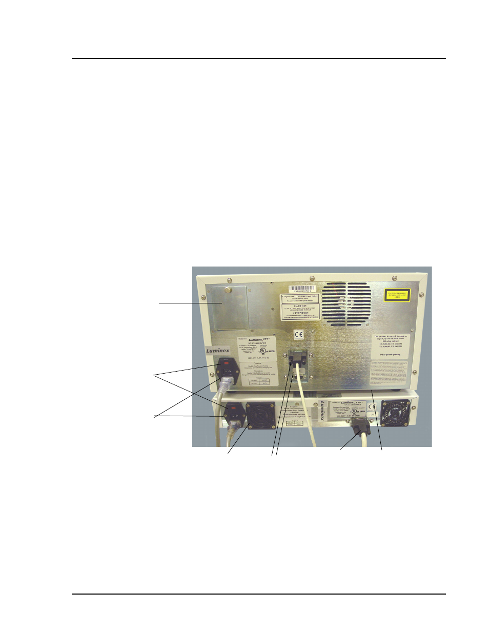
Electronic
Power input module: Houses the analyzer on/off switch and
fuses.
P1 communications port (DB9): Connects the Luminex 100
analyzer to the computer.
Analyzer ventilation filter: Provides filtration for the analyzer
ventilation system. To ensure proper ventilation, do not obstruct the
area below the analyzer. Allow at least two inches of clearance
around the analyzer.
Figure 3-1. Rear View of Luminex 100 Analyzer
Communications
Ports (DB9)
Analyzer
Ventilation Filter
XYP Instrument
Ventilation Filter
Power Input Module
Power Switch
Air Intake Access Door
XYP to PC
Serial cable