Laurel Electronics LAUREATE SERIES 2 COUNTER-TIMER-SERIAL INPUT METER User Manual
Page 42
42
ZERO INDEX SETUP
The relationship between the zero index correction signal and the Channel A & B signals
varies by encoder model and by manufacturer. To accommodate this variation, the Quadra-
ture board has control jumpers and selectable outputs that provide ANDing of the zero index
signal with all possible combinations of the Channel A & B signals.
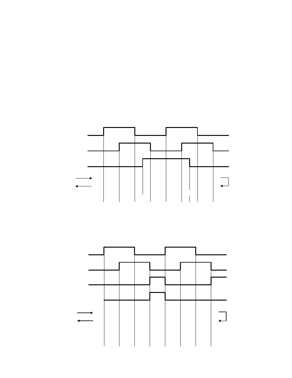
Consider a typical encoder model that produces the waveforms shown below. Assume that
X4 counting is selected. The count increases or decreases with each A & B transition and
remains steady between transitions. The counts shown below the waveforms represent the
effect of the zero index correction ZI if no ANDing is used. Note the difference in count in the
regions between transitions when counting up and then counting down. The zero index
correction is made on the leading edge transition of the zero index signal. When counting
down, the leading edge is the trailing edge of the signal shown below because time is
increasing from right to left.
A Channel
B Channel
Zero Index Pulse
Up Counts
Down Count
Up Region
Down Region
-3
-2
-1
1
4
2
0
3
5
-6
-5
-4
-3
-2
-1 0 3
4
-3
-2
-1
1
2
3
4
-5
-4
-3
-2
-1
0
0
5
5
4
3
Change
Direction
It follows that a wide zero index signal causes a discrepancy in the count in the regions
between transitions when counting up and counting down. To correct this situation, AND the
zero index signal with the A & B channel signals. Assume for this example the zero index is
ANDed with the inverse of A (/A) and the inverse of B (/B) to produce ZIY as shown below.
A Channel
B Channel
ZIY
Zero Index AND ZIY = ZIR
Up Counts
Down Count
Up Region
Down Region
-3
-2
-1
1
4
2
0
3
-4
-3
-2
-1
2
3
4
0
-3
-2
-1
1
2
3
4
0
-3
-2
-1
1
2
3
4
0
ZIR
Change
Direction