Laurel Electronics LAUREATE SERIES 2 COUNTER-TIMER-SERIAL INPUT METER User Manual
Page 22
22
POWER FACTOR MODE (PHASE) (Extended counter)
The power factor of an AC power system is the ratio of real power in watts (W) divided by
apparent power in volt-amperes (VA). For sinusoidal signals differing by a phase angle θ,
power factor will be cos(θ), which is how the meter computes power factor.
Power Factor readings can range from 1.000 to 0.000 with three decimal places and an
accuracy of 0.1% for sinusoidal signals at 50/60 Hz AC line frequency. Maximum
frequency is 1 kHz. While Power Factor is always positive, the meter artificially assigns a
minus sign to Power Factor for negative phase angles, and it sets Power Factor to 0 for
phase angles greater than 90°.
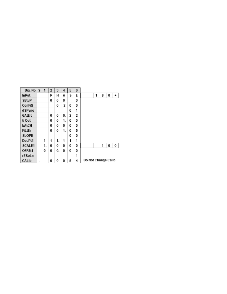
POWER FACTOR MEASUREMENT TO 0.001 RESOLUTION
Application: Display power factor to 0.001
resolution between two AC voltage wave-
forms.
Solution: Use an Extended counter, as for
phase angle measurement. Jumper the
signal conditioner for maximum sensitivity
to catch zero voltage crossings and mini-
mize the effects of amplitude jitter. Apply
AC signals to channels A and B. Set Input
to “PHASE -180+”. Set gate time of 0.22
sec for 4 display updates per sec. Set
Config to 0200, Scale to 1.00000, and
multiplier to 100.
Power Factor is stored in the custom curve section of the Extended counter and uses
"PHASE -180+" as the input type. Setting ConFiG to X1XX sets up for Phase Angle.
Setting ConFiG to X2XX enables Power Factor scaling. First set the unit up as a phase
meter and verify that it is working properly. You will need to set the jumpers on the signal
input board for the signal level to be applied to the A and B inputs.
The decimal point is set for the desired Power Factor display, either xxx.xxx, xxxx.xx or
xxxxx.x . This is one of the instances where decimal point selection is not independent of
the counts displayed.
Power Factor is displayed as a value from -0 to -1 and +1 to +0, with a discontinuity at -1,
+1 corresponding to zero phase angle. As the display traverses the range from -0 to -1
and +1 to +0, an Output Control Value (OCV) is created that extends from 0 to +2.000
with a continuous positive slope and no discontinuity at zero phase angle.
The first half of OCV is created by assuming the absolute value of the display value from
-0 to -1, and hence becomes 0 to +1.000. The second half of OCV is created by
subtracting the displayed value +1 to 0 from 2.000, and hence becomes +1.000 to
+2.000. While never displayed, OCV is the source value for determining the analog
output, for setpoint comparisons, and for filtering purposes, as it eliminates the discon-
tinuity observed at zero phase angle.