Seai/o module common features – Impulse 463N User Manual
Page 13
©Sealevel Systems, Inc.
SL9049 - 11/2010
SeaI/O Manual
13
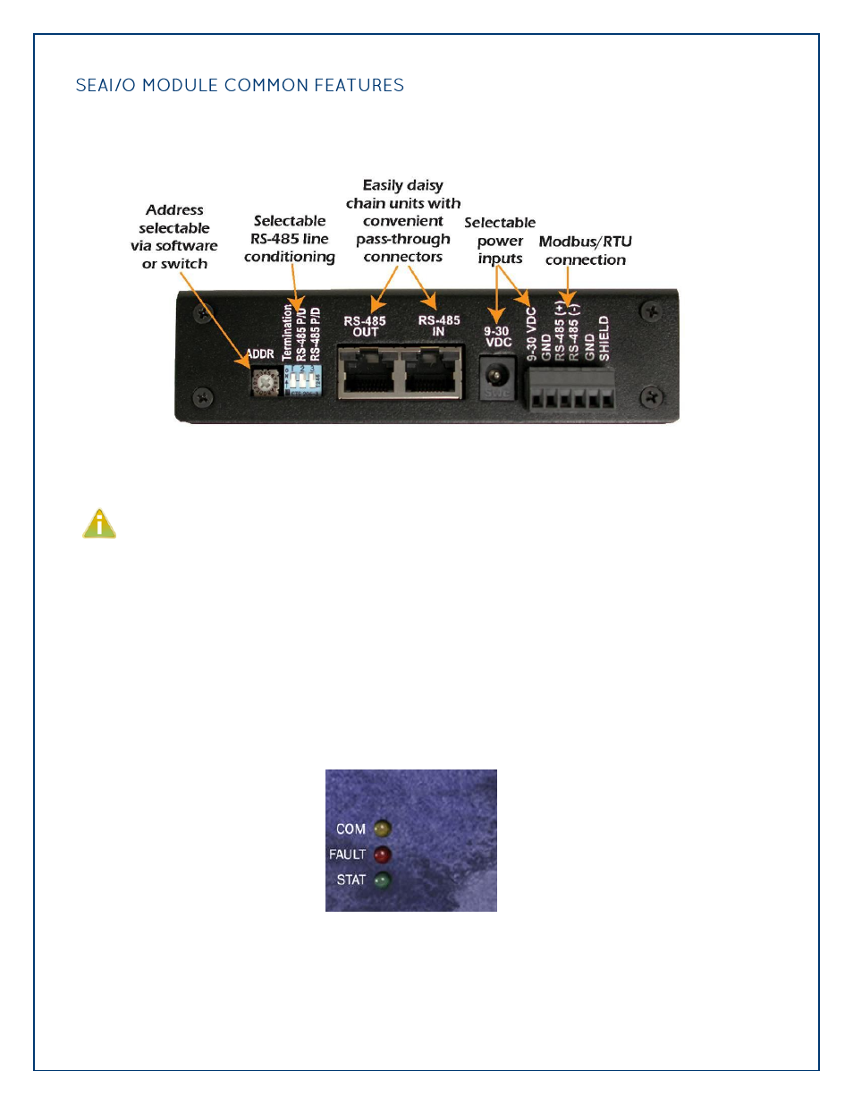
All SeaI/O modules include the same connectors and configuration options on the side of the unit:
RS-485 networks should have termination enabled on each end of the network. Pull-up and
pull-down resistors should also be enabled on the last device on the network. The 9-30VDC
input barrel connector is center positive.
Status LEDs are also included on the front of all SeaI/O modules to indicate the following
information:
Communication (Yellow) – Blinks when data is transmitted
Fault (Red) – Lights when there is a problem with the device
Status (Green) – See Device Address Configuration section of this manual
o Blinks when the rotary “ADDR” switch is set to “0” and the default Slave ID is set to 247
o Lights steady when module is properly configured from the factory defaults