Appendix — wire size schedules, Low voltage control wiring – Controlled Products Systems Group 222EX43 User Manual
Page 80
61
© 2012 Installation and Reference Manual D0119 Rev. J
Appendix
— Wire Size Schedules
For 1/2-hp through 5-hp motors
Supplying a gate operator with the right electrical
service is crucial to the performance of the operator
and the life of its electrical components. If the wire size
used is too small, the voltage loss, especially during
motor startup, will prevent the motor from attaining its
rated horsepower. The percentage of horsepower lost
is far greater than the percentage of voltage loss. A
voltage loss could also cause the control components
to chatter while the motor is starting, substantially
reducing their life due to the resultant arcing. There is
no way to restore lost performance resulting from
undersized wires, except to replace them; Choose a
sufficient wire size at initial installation to avoid costly
rewiring.
The tables on the following page are based on copper
wire and allow for a 5% voltage drop. The ampere
values shown are the service factor ampere rating
(maximum full load at continuous duty) of the motor. A
20A circuit (protected with a 20A Inverse Time Breaker)
should be provided, at minimum.
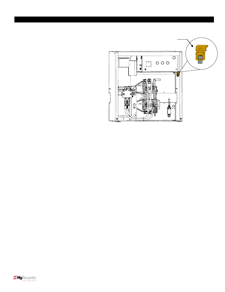
Always connect electrical power and ground the operator in accordance with the National Electrical Code, article
’s 430
and 250 plus other local codes that may apply. For your convenience, a ground lug is mounted on the operator. Use the
ground lug to fastener the ground
wire to the operator’s chassis. See the illustration.
The maximum distance shown is from the gate operator to the power source; assuming that source power is from a panel
box with adequate capacity to support the addition of this motor load. The values are for one operator, with no other loads
applied to the branch circuit. Avoid placing more than one gate operator to a circuit, but if you must, be certain to reduce
the maximum allowed distance by half.
Low Voltage Control Wiring
:
The Smart Touch controller has very sensitive control inputs so the wire size of the control wiring is not a significant
issue.The following is a chart of maximum distances for controls:
Wire Size
Maximum Distance
18 ga
7.0 miles (11km)
20 ga
3.5 miles (5.6km)
22 ga
2.7 miles (4.3km)
24 ga
2.0 miles (3.2km)
26 ga
1.0 mile (1.6km)
28 ga
3700 feet (1.1km)
Ground lug