Controlled Products Systems Group 222EX43 User Manual
Page 35
18
© 2012 Installation and Reference Manual D0119 Rev. J
NOTE: For the 50VF2-EFO,
refer to the setup and
programming instructions on
page 20.
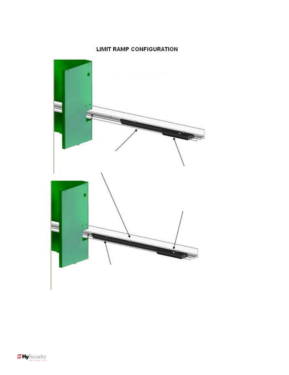
11.5″ limit ramp placed along the inside
channel with the tapered end toward the
wheels and the flat end out.
30″ limit ramp placed in the outside
channel with the tapered end toward the
wheels and the flat end out.
An additional 10.5
″ double-tapered limit
ramp is placed in the outside channel
on the 50VF3 and 50VF2-EFO models.
SlideDriver 50VF2 (X2)
SlideDriver 50VF3 (X3)
SlideDriver 50VF2-EFO (X2EFO)
Flanged drive rail
shown. Standard
drive rail no longer
has flanges, but does
have a grooved
surface. Two bolts
required to secure
limit ramp.
2X
2X
2 bolts
secure
limit
ramp.