Controlled Products Systems Group 222EX43 User Manual
Page 29
12
© 2012 Installation and Reference Manual D0119 Rev. J
Section 2
— Installation
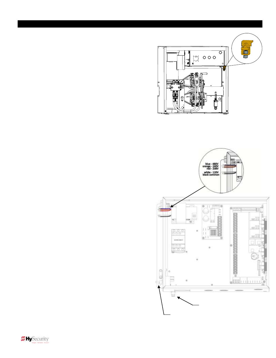
6. Grounding
Make sure that the ground rod installation meets NEC, NFPA 780
and local building standards and codes. Attach a large earth
ground wire (6AWG) from the grounding rod to the ground lug on
the chassis. Properly grounding the gate operator is critical to gate
operator performance and the life of its electrical components. Use
sufficient wire size during installation.
7. Electrical Power Connection
This operator is intended for permanent installation. All electrical
conduits must be properly connected to the control box. The entry
for the primary power is a ½ - ¾-inch knockout on the left side of
the control box next to the power switch. The operator is built to run
on a specific voltage and phase. Make sure you have compared
the available line voltage and phase with the voltage and phase
listed on the nameplate on the machine. They must match! Be
certain that the branch circuit wire size versus the distance of the run from the main panel is large enough to avoid
excess voltage drop. At a minimum, a 20A circuit (protected with a 20A Inverse Time Breaker) should be provided.
Also be sure the operator is electrically grounded per NEC Article 250 and local codes. See page 62 for correct wire
sizes and detailed electrical wiring information.
8. Primary Tap of Control Transformer
Check to make sure that the primary tap on the control transformer matches the line
voltage you have connected to the operator. Measure the line voltage carefully to
distinguish between 208V and 230V branch circuits or between 390V and 460V branch
circuits. A label on top of the transformer identifies the various voltage taps. This
connection must match the voltage on the operator nameplate.
NOTE: Primary taps do not exist on battery operators.
9. Electrical Power for Two Part 333-type operators
The primary AC power must be routed to the controller enclosure with the
pump, but there must also be conduits between the gate operator
and the controller enclosure.
NOTE: A minimum of two separate conduits must be provided,
2-inch for the hydraulic hoses and ¾-inch for the electrical
interconnections. Unless there are accessories in the gate
operator, the only electrical interconnection between the two
enclosures will be three wires between the two terminal strips for
the limits switches. AC Power is not needed in the gate operator,
unless there is an optional heater. Join the hydraulic hoses by
plugging the quick coupling together according to the hand of the
gate. See the technical drawing on pages 59 and 60.
10. Connections for Two Part Battery Operators
The primary AC power must be routed to the DC power supply
enclosure, but there
must also be at least one 2” conduit between
the gate operator and the DC supply enclosure. Note: AC power
is not needed in the gate operator enclosure, unless there is an
optional heater. Three separate DC circuits are required between
the battery supply and the gate operator. Heavy gauge wires to
supply the motor and two 14-gauge circuits for the controls. The
heavy gauge wire must be at least 6-gauge if the DC supply is
within 20 feet of the operator, but must be increased to 2-gauge if
the DC supply is located farther from the operator or this is a SlideDriver
30F (222 EX 1.7)
– 1.7ft/sec model. Also see page 55 titled “Important:
DC Powered Gate Operators" and Drawing E125.
Power switch
Reset switch
Ground lug