Controlled Products Systems Group 222EX43 User Manual
Page 11
iv
© 2012 Installation and Reference Manual D0119 Rev. J
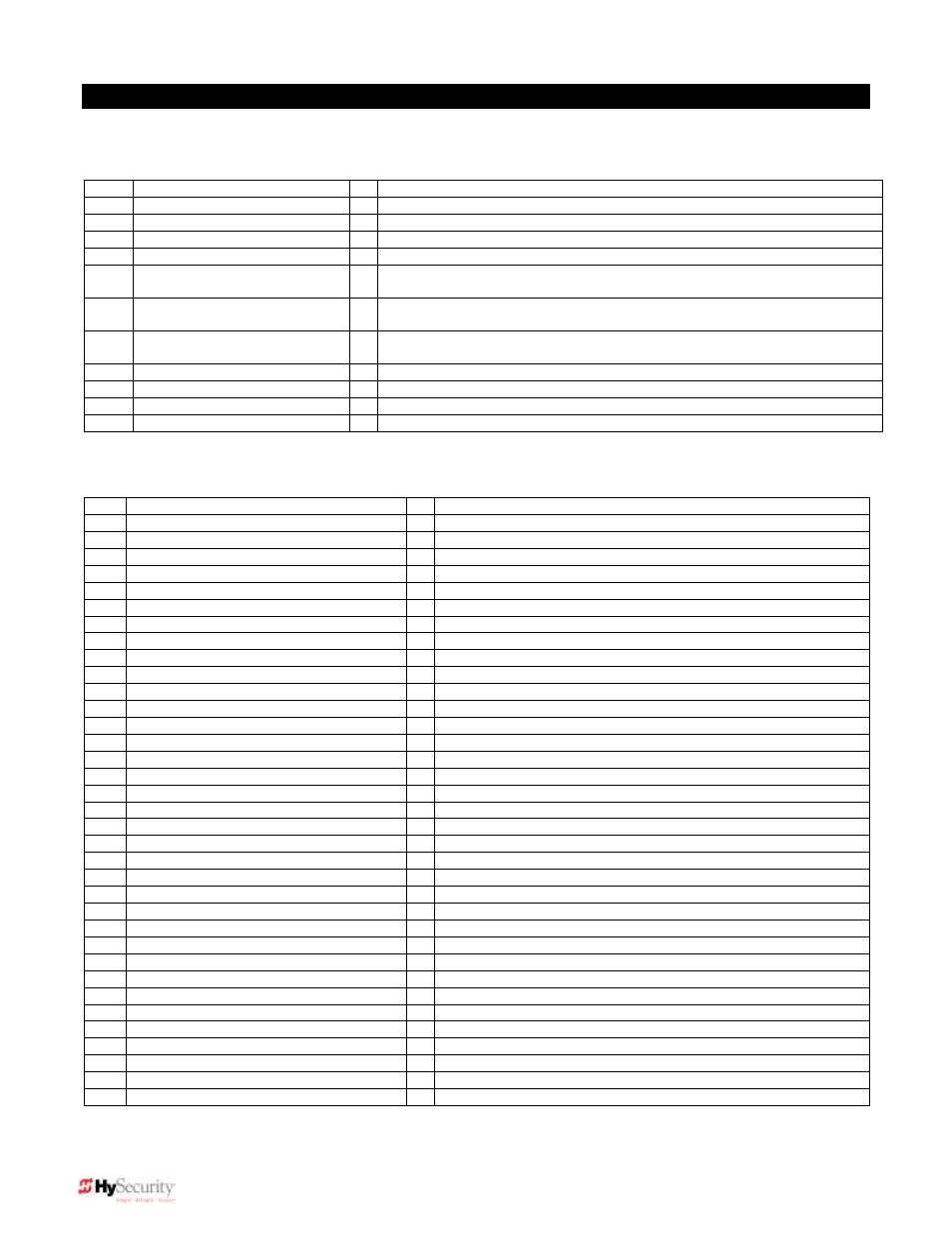
Smart Touch Controller Menu Guide for Sliding Gates
To gain access to the User Menu, press the PROGRAM button when the gate is stopped. The display scrolls
through several operator status items, and then stops at the Close Timer menu setting [
].
User Menu Options
Default
Description
U1
[Ct 0] Close timer setting
0
0 = close timer off or 1 – 99 seconds
U2
[hC 0] Momentary Close
0
0 = momentary, 1= Constant hold PB required to close gate
U3
[ho 0] Momentary Open
0
0 = momentary, 1= Constant hold PB required to open gate
U4
[AP 0] Power loss function
0
0 – 3 (0 =Type A, 1 = B, 2 = C, 3 = D)
U5
[ro 0] Radio control option
0
0 = Open only, 1 = Adds Close capability when fully open
U6
[bF 2] Warn before operate
2
0 = none, 1 = Buzzer alerts 3 sec before & when in motion, 2 = Buzzer alerts
3 sec before + first 2 seconds in motion
U7
[FA 0] Forced open Alert and
automatic gate reposition
0
0 = disabled, 1 = sound buzzer (2 pulses/sec) if forced
open for more than four seconds, time out in 30 Sec
U8
[dA 0] Drift Closed Alert and
automatic gate reposition
0
0 = disabled, 1 = sound buzzer (2 pulses/sec) if drift closed and cannot reopen within
four seconds.
U9
[PE 0] Photo Eye Align Mode
0
0 = off, 1 = on (auto off when close limit triggered)
U10
[CL 0] Clock set (24 hour type)
0
0= display, 1= set minutes, 2= set hours, 3= set day, 4= month
U11
[Ld 5] LCD Contrast set
5
1 - 9 = Adjusts contrast of the display
U12
[dS 0] Data Log
0
0 = Std. 1 = Extended (resets automatically to 0 in 24 hr) (V4.xx software)
To access the Installer Menu, simultaneously press the RESET & OPEN buttons. See page 18 for clarification.
Installer Menu Options
Default
Description
I1
[uC 0] Set UL Usage Class
0
0 = gate disabled, Set Class 1 through 4 use
I2
[Sh 0] Set Handing of gate
0
0 = gate disabled, r = Right Hand, L = Left Hand
I3
[Fd 0] Load Factory Defaults
0
0 = User settings, 1 = Load defaults (resets entire menu)
I4
[bu 0] Choose Buzzer Type
0
0 = Buzzer not set, 1 = Freq 1, 2 = Freq 2
I5
[dg 0] Set dual gate type
0
0 = Solo operator, 1 = Slave, 2 = Master, 3 = Sally PortA, 4 = Sally PortB
I6
[SG 0] Set sequential gate
0
0 = not active, 1 = Loop Layout #1, 2 = Loop Layout #2
I7
[Ch 0] Set AC Charger or Solar
0
0 = DC + AC charger 1 = DC + Solar charger
I8
[Fo 0] Enable Fire Dept. Open
0
0 = input disabled, 1 = enabled
I9
[oC 0] Enable Emergency close
0
0 = input disabled, 1 = enabled
I10
[SE 3] Inherent Sensor sensitivity
3
1 = Maximum sensitivity, 9 = Lowest sensitivity
I11
[SS 0] Inherent Sensor function
0
1 = stop only (note, functions in usage class 4 only)
I12
[LC 0] Leaf delay Close
0
0 = none (1-7) ½ second steps (Master/slave only)
I13
[Lo 0] Leaf delay Open
0
0 = none (1-7) ½ second steps (Master/slave only)
I14
[rt 0] Maximum run timer
0
0 = 60 Seconds max run, 1 = 300 Seconds max run
I15
[Po 0] Partial Open distance
0
0 = input disabled, or 7 – 99 seconds of travel
I16
[EC 0] PEC reverse to open
0
0 = Close eye stops only, 1 = 2 sec reverse to open
I17
[EO 0] PEO reverse to close
0
0 = Open eye stops only, 1 = 2 sec reverse to close
I18
[gr 0] Edge reverse to open
0
0 = Edge reverses fully open, 1 = Edge reverses for 2 sec
I19
[Sr 1] IES reverse to open
1
0 = IES reverses fully open, 1= IES reverses for 2 sec
I20
[PC 0] Set PEO/ PEC
– NO/NC
0
0 = Normally Open PE output, 1 = N.C. (Supervised mode)
I21
[gC 0] Set Edge input
– NO/NC
0
0 = Normally Open Edge output, 1 = Normally Closed
I22
[tC 1] Time clock/ Interlock input
1
0 = select Time Clock, 1 = select Open Interlock
I23
[dt 0] Disable Free Exit/Timer to Close
0
0 = disable Free Exit, 1 = disable Close Timer
I24
[or 1] OOLD detector function
1
0 = pause closing only, 1 = enable reversing to open
I25
[ir 1] IOLD detector function
1
0 = pause closing only, 1 = enable reversing to open
I26
[dL 1] Vehicle detector logic
1
1 = std, 2 & 3 = quick close, 4 = full anti-tailgate logic
I27
[r1 0] User relay 1 option
1
0 = disabled, 1 – 24 = see output options page 30
I28
[r2 0] User relay 2 option
6
0 = disabled, 1 – 24 = see output options page 30
I29
[r3 0] User relay 3 option
1
0 = disabled, 1 – 24 = see output options page 30
I30
[tL 0] Gate Open alert
2
0 = 0 sec, 1 = 15s, 2 = 45s, 3 = 75s, 4 = 105s, 5 = 135s
I31
[Lt 0] Loitering alert
3
0 = 0 sec, 1 = 15s, 2 = 45s, 3 = 75s, 4 = 105s, 5 = 135s
I32
[SA 0] System address
0
0 = no network, 1-99 = network “drop” address
I33
[ELd0] Test factory ELD
0
0=Run, 1=show freq, 2=show call level 0-7, 3= set Freq 1-4
I34
[iLd0] Test factory IOLD
0
0=Run, 1=show freq, 2=show call level 0-7, 3= set Freq 1-4
I35
[oLd0] Test factory OOLD
0
0=Run, 1=show freq, 2=show call level 0-7, 3= set Freq 1-4
I36
[SLd0] Test factory SLD
0
0=Run, 1=show freq, 2=show call level 0-7, 3= set Freq 1-4