Main board, Measurement board, Figure 3 – Hach-Lange ORBISPHERE 510_51x Basic User Manual User Manual
Page 10
Main board
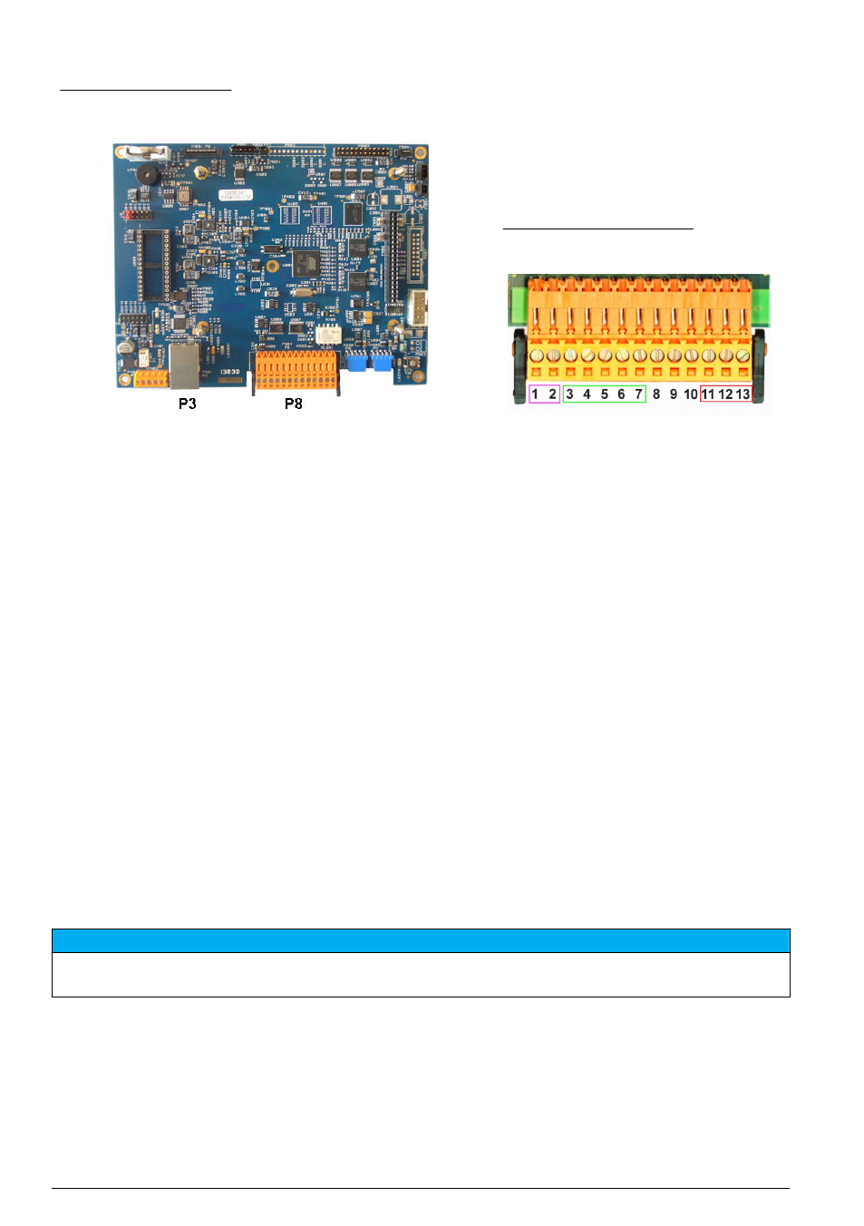
Figure 3 Main board
Figure 4 Connector P8
Connector P8
The numbers listed below refer to the 13 available P8 connections (from left to right) in
1. RS-485 (signal A)
2. RS-485 (signal B)
3. PROFIBUS-DP (GND)
4. PROFIBUS-DP (+ 5 V)
5. PROFIBUS-DP (signal -)
6. PROFIBUS-DP (signal +)
7. PROFIBUS-DP (signal RTS)
8. Not used
9. Not used
10. Not used
11. System alarm relay (N.O.)
12. System alarm relay (N.C.)
13. System alarm relay (Common)
Connector P3
Ethernet RJ 45. Connect the wall and panel mount instruments to the local network by passing an
ethernet cable through the ethernet cable gland (gland location illustrated in
on page 7) and
connecting to the P3 connector illustrated in
.
Note: For portable instruments, the ethernet connection is located on the back panel (see
on page 7). A waterproof Harting RJ industrial socket is provided to fit to a client network cable. Accessory adapter
and cable are available as an option.
Measurement board
The different measurement boards for the EC and TC sensors are illustrated in
and
. The type of board is easily identified by the color of the J8 connector. For EC boards this
connector is colored orange, and for TC boards it is colored black.
N O T I C E
It is extremely important that sensors are connected to the correct measurement board. Connecting a TC sensor
to an EC measurement board (and vice versa) will cause irreparable damage to the measurement board.
10 English