Power, Installation, Removal – GF Signet 8059 External Relay Modules User Manual
Page 2: Warning, N l ac power terminals, Dc power terminals
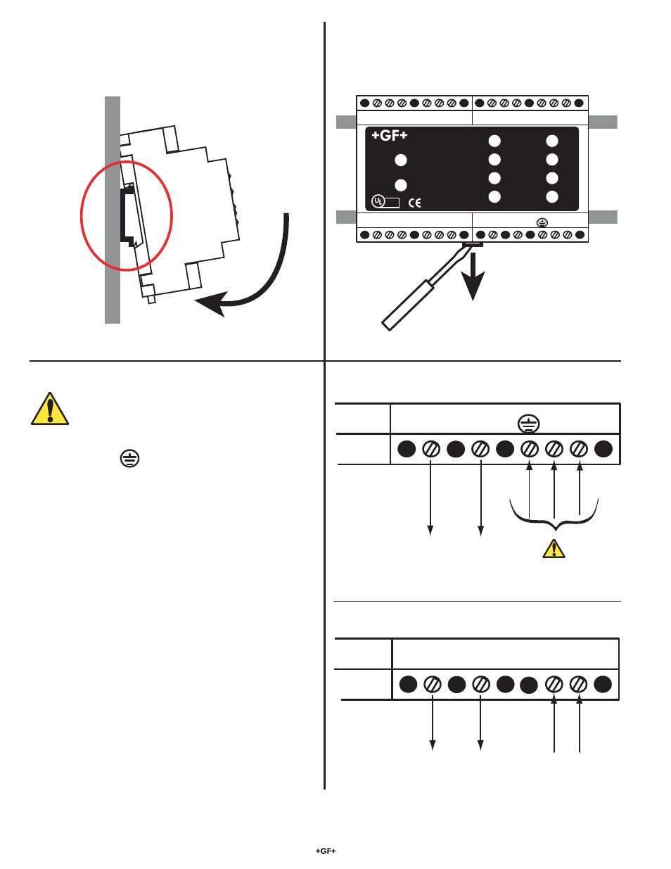
Signet 8059 External relay module
2
4. Power
OUTPUT 24VDC
+ -
AC INPUT
N L
AC Power terminals
100 - 240 VAC
50/60 Hz, 20 VA
24 VDC Regulated,
300 mA maximum
DC OUTPUT
+ -
DC INPUT
- +
DC Power terminals
12 to 24 VDC
100 mA maximum
Pass-through DC
(less 0.7 VDC)
3. Installation
Tilt top of the 8059 to insert under top DIN rail, then press bottom
of 8059 until the locking pin snaps onto lower DIN rail.
Removal
Insert screwdriver into release mechanism on bottom of 8059.
Pull down on release while lifting 8059 away from the DIN rail.
•
This unit must be installed inside a protected panel.
•
Always connect to earth ground.
•
Disconnect power before wiring.
•
Do not install where persons may inadvertently come in
physical contact with the terminals.
•
Include protection devices in the power system in case of
power supply malfunction. A very high voltage may occur at
output terminals during failure.
•
Do not touch immediately after removing power. Some
surface areas may be very hot.
•
Do not exceed temperature specifi cations.
•
Do not store or operate the AC power supply in any
environment subjected to vibrations or shock.
WARNING
NC C NO
RELAY A
NC C NO
RELAY B
NC C NO
RELAY C
NC C NO
RELAY D
+
S
3
L
-
+
S
3
L
-
OUTPUT 24VDC
+ -
AC INPUT
INPUT
PASS-THRU
L N
COM
32:(5
Signet 3-8059 Relay Module
Test A
Test B
Test C
Test D
Relay A
Relay B
Relay C
Relay D
LISTED
E171559
®