Cell constant selection, Range selection for 4 to 20 ma output, 10 cell – GF Signet 2850 Conductivity-Resistivity Sensor Electronics and Integral System User Manual
Page 5: Co o, 0 to 100 μs
5
2850 Conductivity/Resistivity Sensor Electronics
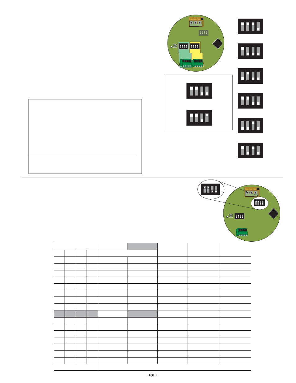
• The Range selection switch bank (SW2) provides eight range
selections for each cell constant. Each range can be inverted,
making a total of 16 range options.
• Select a range from the table below and set SW2 as indicated.
O = Open
C = Closed
Example (refer to shaded selections of chart):
• The electrode installed is the 3-2840-1, with a 0.10 cell constant.
• The required output is 4 to 20 mA = 0 to 100 μS.
• Set SW2 switch bank to C-C-O-O.
• To invert range (4 to 20 mA = 100 to 0 μS), close switch #4.
1
2
3
4
ON
CTS
1
2 3
S
W1
SW3
SW4
D3
1
2
3
4
ON
CTS
1
2
3
4
ON
CTS
1
2
3
4
ON
CTS
1
2
3
4
ON
CTS
1
2
3
4
ON
CTS
1
2
3
4
ON
CTS
1
2
3
4
ON
CTS
1
2
3
4
ON
CTS
1
2
3
4
ON
CTS
Ch 1
Ch 2
1
2
3
4
ON
CTS
0.01/cm-1
0.1/cm-1
1.0/cm-1
10.0/cm-1
20.0/cm-1
Open
Closed
Open
Closed
Closed
Open
Closed
Open
Closed
Open
Closed
Open
Closed
Open
Example: 1.0 cell constant, temp comp ON
Example: 1.0 cell constant, temp comp OFF
Closed
Open
Custom Cell Constant
8. Cell Constant Selection
Cell Constant Selection
• The 2850 is shipped from the factory with the custom cell
constant and temperature offset programmed into the single-
input electronics. SW3 will be preset to "Custom cell constant".
• Switch banks SW3 and SW4 are used to select the cell
constant of the electrode. The Dual Input model is illustrated.
Single input models use only SW3.
• Make all switch settings before connecting power. Switch
changes made with the power ON will take 15 to 20 seconds
before becoming effective.
• Use SW3 #1-3 to select the cell constant for the fi rst sensor.
• Use SW3 #4 to disable the PT1000 Temp Compensation
function in the 2850 (as required for USP applications.) This
disables the function for BOTH INPUTS.
• Use SW4 #1-3 to select the cell constant for the second sensor.
• Set SW4 #4 to OPEN to disable the second input.
SW1
SW2
SW2
SW3
D3
1
2
3
4
ON
CTS
1
2
3
4
ON
CTS
1
3
2
1
2
3
4
ON
CTS
SW3 Cell Constant and Temp Compensation
#1 #2 #3 #4 For
Cell
Constant
C C C O Custom
C O O O 0.01
cm
-1
O C O O 0.1
cm
-1
C C O O 1.0
cm
-1
O O C O 10.0
cm
-1
C O C O 20.0
cm
-1
#4:
Open = Temp Comp ON
Closed = Temp Comp OFF
SW4: #1, #2 and #3 operate the same as SW3.
#4 turns input 2 OFF when set to OPEN.
(Open = Off, Closed = On)
9. Range Selection for 4 to 20 mA Output
SW2 Switch Setting
0.01 Cell
0.10 Cell
1.0 Cell
10.0 Cell
20.0 Cell
#1
#2
#3
#4
Resistivity Ranges in BOLD
C
C
C
O
10 to 20 MΩ
0 to 2 μS
0 to 20 μS
0 to 200 μS
0 to 400 μS
C
C
C
C
20 to 10 MΩ
2 to 0 μS
20 to 0 μS
200 to 0 μS
400 to 0 μS
O
C
C
O
2 to 10 MΩ
0 to 5 μS
0 to 50 μS
0 to 500 μS
0 to 1000 μS
O
C
C
C
10 to 2 MΩ
5 to 0 μS
50 to 0 μS
500 to 0 μS
1 000 to 0 μS
C
O
C
O
0 to 2 MΩ
0 to 10 μS
0 to 100 μS
0 to 1 000 μS
0 to 2 000 μS
C
O
C
C
2 to 0 MΩ
10 to 0 μS
100 to 0 μS
1 000 to 0 μS
2 000 to 0 μS
O
O
C
O
0 to 1 μS
0 to 50 μS
0 to 5 000 μS
0 to 5 000 μS
0 to 10 000 μS
O
O
C
C
1 to 0 μS
50 to 0 μS
500 to 0 μS
5 000 to 0 μS
10 000 to 0 μS
C
C
O
O
0 to 5 μS
0 to 100 μS
0 to 1 000 μS
0 to 10 000 μS
0 to 20 000 μS
C
C
O
C
5 to 0 μS
100 to 0 μS
1 000 to 0 μS
10 000 to 0 μS
20 000 to 0 μS
O
C
O
O
0 to 10 μS
0 to 200 μS
0 to 2 000 μS
0 to 50 000 μS
0 to 100 000 μS
O
C
O
C
10 to 0 μS
200 to 0 μS
2 000 to 0 μS
50 000 to 0 μS
100 000 to 0 μS
C
O
O
O
0 to 50 μS
0 to 500 μS
0 to 5 000 μS
0 to 100 000 μS
0 to 200 000 μS
C
O
O
C
50 to 0 μS
500 to 0 μS
5 000 to 0 μS
100 000 to 0 μS
200 000 to 0 μS
O
O
O
O
0 to 100 μS
0 to 1 000 μS
0 to 10 000 μS
0 to 200 000 μS
0 to 400 000 μS
O
O
O
C
100 to 0 μS
1000 to 0 μS
10 000 to 0 μS
200 000 to 0 μS
400 000 to 0 μS
C = CLOSED O = OPEN
Switch #4 inverts the output: OPEN = 4 to 20 mA, CLOSED = 20 to 4 mA
NOTE: To work correctly
with the 9900, the 2850 must
be set for the custom cell
constant or the actual probe
cell constant and the 9900
set for a 1.0 cell constant.