L) output version 7. wiring dual input digital (s, L) output version, Dual input is available on digital s – GF Signet 2850 Conductivity-Resistivity Sensor Electronics and Integral System User Manual
Page 4: 9 vdc to 26 vdc, 20 ma loop output
4
2850 Conductivity/Resistivity Sensor Electronics
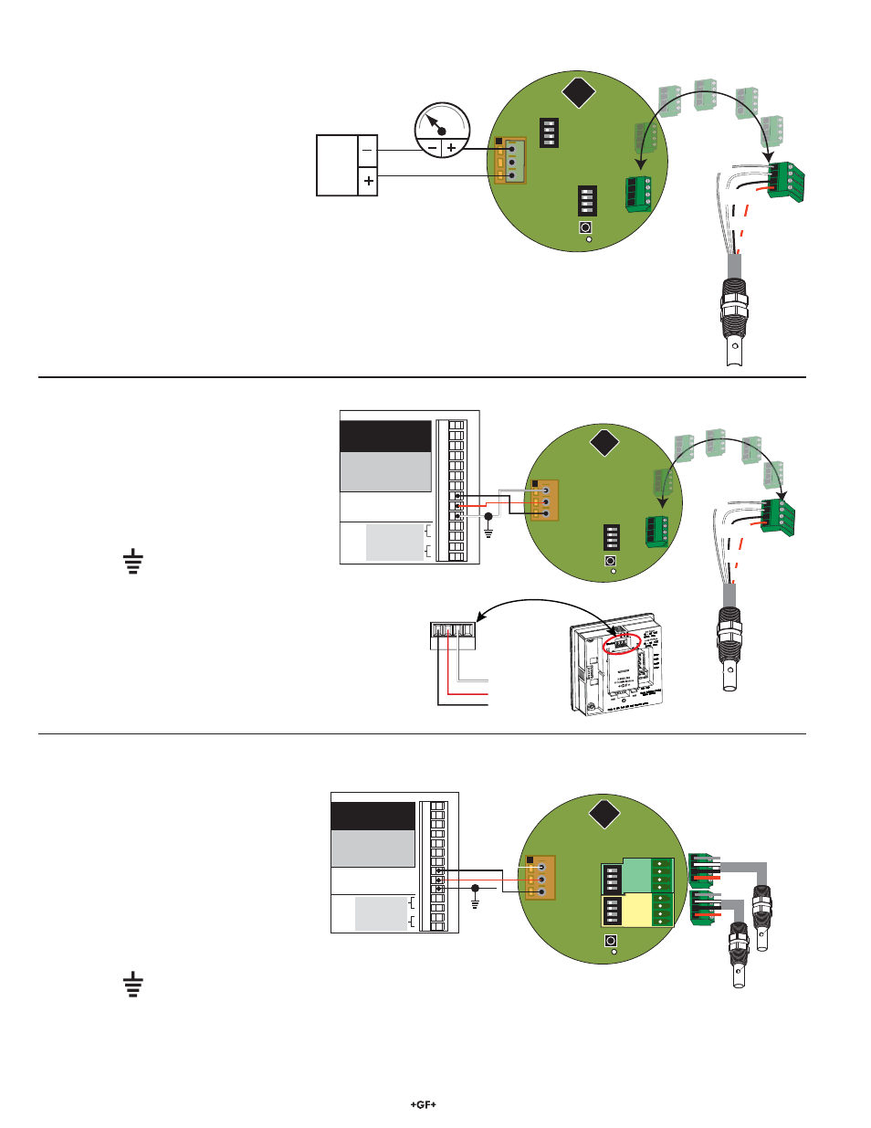
5. Wiring 4 to 20 mA Output Version
6. Wiring Digital (S
3
L) Output Version
7. Wiring Dual Input Digital (S
3
L) Output Version
• Dual input is available on Digital S
3
L output
model 3-2850-63 only, for use with the
Signet 8900 Multi-Parameter Controller.
• Sensors may be the same or different cell
constants.
• If the dual input model is used with a single
sensor, connect the sensor to channel 1 and
set all of the channel 2 switches to OFF.
• IMPORTANT: Provide Earth Ground as
indicated by
symbol.
• The digital output is compatible with the
Signet 8900 Multi-Parameter Controller and
the Signet 9900 Transmitter.
• Refer to the wiring sections of the 8900
or 9900 manual to determine cable length
limitations.
• IMPORTANT: Provide Earth Ground as
indicated by
symbol.
• Maximum length of 4 to 20 mA loop is 300 meters (1000 ft)
SW1
D3
1
2
3
1
2
3
4
ON
CTS
1
2
3
4
ON
CTS
4 20
V-
V+
Temp. IN
(WHITE)
Sensr Gnd
(SHIELD)
Signal IN
(RED)
Signal RTN
(BLK)
9 VDC
to
26 VDC
4-20 mA Loop Output
SW1
D3
1
2
3
1
2
3
4
ON
CTS
3-8900.621C
I/O Module 3-8900.401-X
1
2
3
4
5
6
7
8
9
10
11
12
13
14
+5VDC (Black)
Freq. Input (Red)
GND (Shield)
+5VDC (Black)
Freq. Input 2 (Red)
S L (Red)
GND (White/Shield)
+5VDC (Black)
S L (Red)
GND (White/Shield)
3
3
Analog Output 1
Analog Output 2
(if applicable)
(if applicable)
Frequency
Input
1
Frequency
Input 2
OR
S3L
Input
2
S3L
Input
1
+
-
+
-
V+
DA
T
A
GND
SHLD
V+
DC Power
Loop V
oltage
3-9900.395
H COMM Module
Gnd
Data
Temp. IN
(WHITE)
Sensr Gnd
(SHIELD)
Signal IN
(RED)
Signal RTN
(BLK)
Black
Red
White
9900 S
3
L Input
SW1
D3
1
2
3
1
2
3
4
ON
CTS
1
2
3
4
ON
CTS
V+
3-8900.621C
I/O Module 3-8900.401-X
1
2
3
4
5
6
7
8
9
10
11
12
13
14
+5VDC (Black)
Freq. Input (Red)
GND (Shield)
+5VDC (Black)
Freq. Input 2 (Red)
S L (Red)
GND (White/Shield)
+5VDC (Black)
S L (Red)
GND (White/Shield)
3
3
Analog Output 1
Analog Output 2
(if applicable)
(if applicable)
Frequency
Input
1
Frequency
Input 2
OR
S3L
Input
2
S3L
Input
1
+
-
+
-
Gnd
Data
Ch 1
Ch 2
Sensor 1
Sensor 2
Note: The 2819-2823 and 2839-2842 sensors
can connect directly to the 9900 via the 9900's
optional Direct Conductivity/Resistivity Module
3-9900.394 (159 001 699).