Calibrate menu – GF Signet 8860 Dual Channel Conductivity-Resistivity Controller User Manual
Page 6
6
8860 Dual Channel Conductivity/Resistivity Controller
Select CUSTOM only if you are connecting a certifi ed conductivity sensor. Select
STANDARD for all non-certifi ed sensors.
For STANDARD sensors: Select the nominal cell constant: 0.01, 0.1, 1.0, 10.0 or 20.0.
For CUSTOM sensors: Enter the precise cell constant from the certifi cate provided with your
sensor, or from the information label on the sensor.
Adjust the temperature of the system based on an accurate external reference.
This single-point wet calibration procedure requires a test solution of known value.
Enter all zeroes here to restore TEMPERATURE and CONDUCTIVITY to factory calibration.
Select the units of measure: μS/cm, mS/cm, kΩ•cm, MΩ•cm, PPB, PPM
If the Units selection is PPM or PPB, set the ratio of μS to Total Dissolved Solids. The factory
preset value is 2 μS per 1 PPM of TDS. (Always μS/PPM, even if units is PPB).
See page 10 for additional information.
Select a functional relationship between C1 and C 2: • Ratio is (C1:C2) or (C2:C1)
• Percent Reject is 100%(1-C2/C1) or 100%(1-C1/C2) • Difference is (C1-C2) or (C2-C1)
Select the measured value or calculated FUNCTION you want Loop 1 to represent:
Chan 1 Cond, Chan 2 Cond, Chan 1 Temp, Chan 2 Temp, or Function
Set the minimum (4 mA =) and maximum (20 mA =) range for Loop 1.
Make sure that the values are consistent with the units of the source.
Select operating mode for Relay 1: OFF, LOW, HIGH, USP or PULSE.
For USP mode: • Relay 1 SOURCE must be Cond 1 or Cond 2
• Temp Comp (Options menu) must be set to None
Select the INPUT SIGNAL (or FUNCTION) monitored by Relay 1:
• Cond 1
• Cond 2
• Temp 1
• Temp 2
• Function
Set Relay 1 activation point. The maximum value acceptable is 999999.
USP setpoints are high alarms, where the setpoint is a percentage below the USP limit.
Relay 1 will be deactivated at setpoint ± Hysteresis (depending on High or Low selection).
When the relay Mode is USP (defi ned as a HIGH alarm), Hysteresis is displayed in μS.
Set up to 6400 seconds delay time for relay response.
Relay 1 will be activated only if the source value exceeds the setpoint for this time period.
If Relay 1 is PULSE mode, set the start and end point of the conductivity range and also set
the maximum pulse rate. (The maximum PULSE rate setting is 400 pulses per minute.)
The combined Relay 1 Range and Pulse rate settings shown here indicate:
"Start pulsing when the conductivity value is 10 μS and increase the pulse rate up to the
maximum of 120 pulses per minute when the conductivity value reaches 40 μS"
Use this "notepad" to record important dates, such as annual recertifi cation or scheduled
maintenance.
Chan 1 Cell:
Standard >
Chan 1 Cell:
1.0 >
Cell: Custom
1.0000 >
Chan 1 Set:
Temperature >
Chan 1 Set:
Conductivity >
Chan 1 Units:
uS/cm >
Chan 1 TDS:
2.0000 uS/PPM
>
Function:
Reject
C1
→ C2
>
Loop 1 Source:
Chan 1 Cond
>
Loop 1 Range: uS
0.0000 → 100.000 >
Relay 1 Mode:
Low >
Relay 1 Source:
Chan 1 Cond
>
Relay 1 Setpnt:
10.0000
uS >
Relay 1 Hys:
0.5000
uS >
Relay 1 Delay:
10.0
secs >
Relay 1 Rng: uS
10.0000 → 40.0000 >
Relay 1 PlsRate:
120 Pulses/Min
>
Last CAL:
04-20-08 >
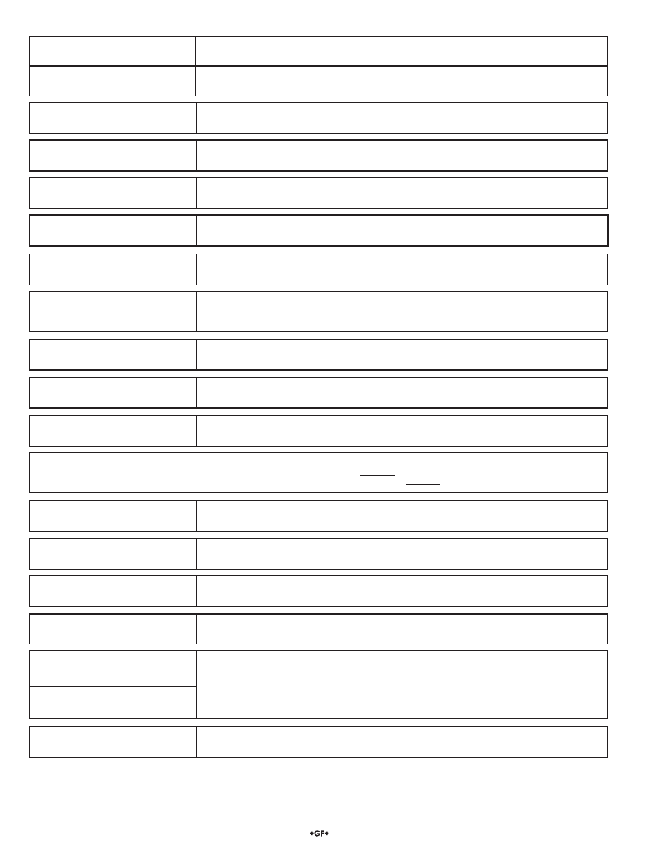
Calibrate Menu
Display
(Factory settings shown)
Description
• All changes in this menu become effective when saved, except the "Set Cond" and "Set Temp" settings.
• All outputs affected by a change in the "Set Cond" and "Set Temp" settings are frozen until you exit the Calibrate menu.