Loop 1 loop 2 loop 3, Electrical connections, Output option switch – GF Signet 8860 Dual Channel Conductivity-Resistivity Controller User Manual
Page 2
2
8860 Dual Channel Conductivity/Resistivity Controller
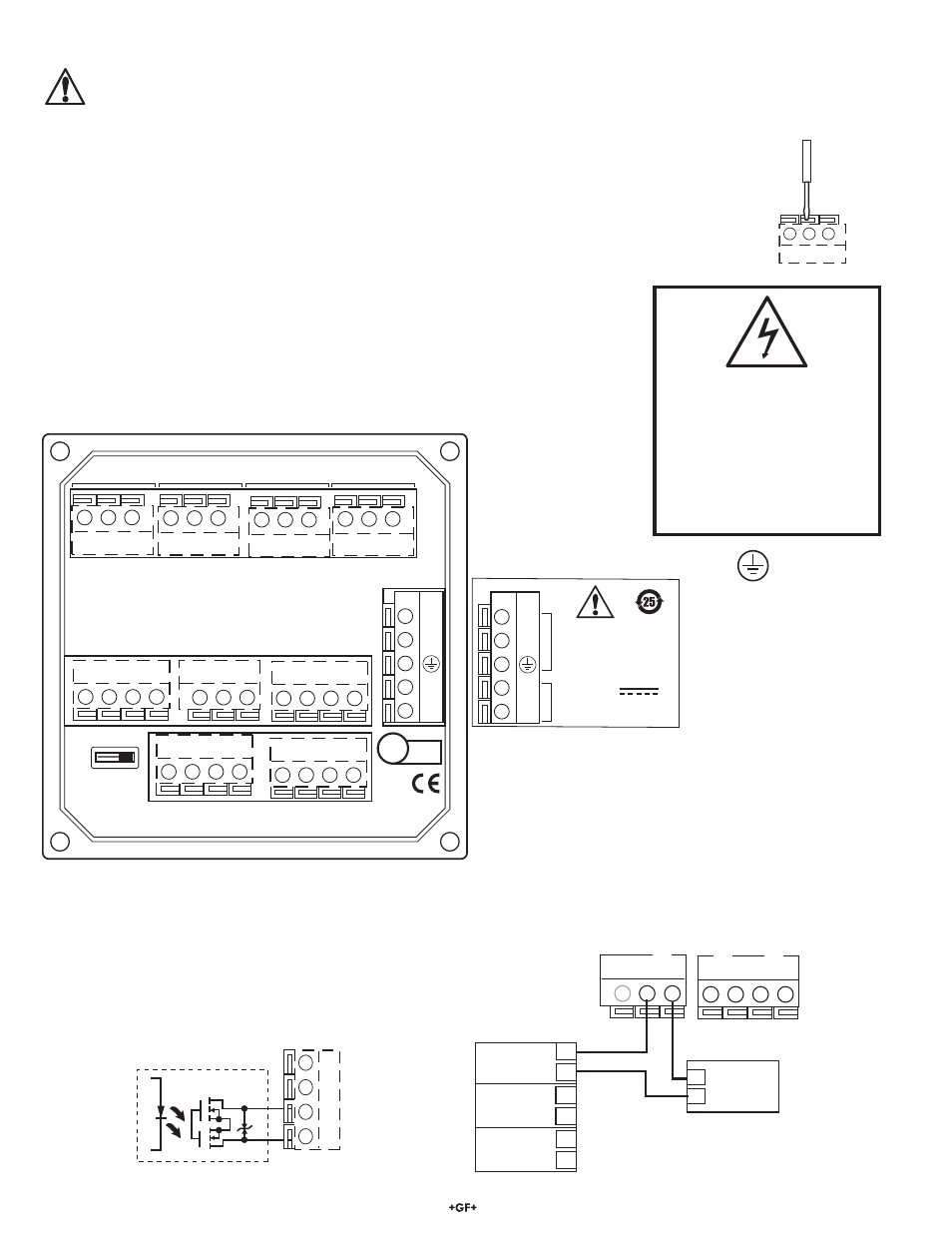
Electrical Connections
Caution: Failure to fully open terminal jaws before removing wire may permanently damage instrument.
This product must be provided with a means to disconnect all current carrying conductors connected to the main AC line, or,
as part of the building installation.
Wiring Procedure
1. Remove 9 mm to 12 mm (0.35 in. to 0.47 in.) of insulation from wire end.
2. Press the orange terminal lever downward with a small screwdriver to open terminal jaws.
3. Insert exposed (non-insulated) wire end in terminal hole until it bottoms out.
4. Release orange terminal lever to secure wire in place. Gently pull on each wire to ensure a good connection.
Wiring Removal Procedure
1. Press the orange terminal lever downward with a small screwdriver to open terminal jaws.
Wiring Tips:
• Do not route sensor cable in conduit containing AC power wiring - electrical noise may interfere
with sensor signal.
• Routing sensor cabling in grounded metal conduit may prevent moisture damage, electrical
noise, and mechanical damage.
• Seal cable entry points to prevent moisture damage.
• Do not insert two wires into a single terminal. If necessary, splice the wires together before
inserting into the terminal.
RELAY 1
RELAY 2
RELAY 3
RELAY 4
N/C N/O COM
N/C N/O COM
N/C N/O COM
N/C N/O COM
RELA
Y
3,4
OPEN
COLL
3,4
- OPEN COLL
4
+
OPEN COLL
4
-
OPEN COLL
3
+
OPEN COLL
3
-
LOOP
2
+
LOOP
2
-
LOOP
3
+
LOOP
3
-
LOOP
1
+
LOOP
1
SHLD
ISO GND
TEMP
1
SGNL
1
SHLD
ISO GND
TEMP
2
SGNL
2
POWER
OUTPUT
OPTION
L
N
-
+
11 - 24V
0.5 A
L
N
-
+
3-8860.610 D
100 - 240V
50-60Hz, 20VA
~
LISTED
E171559
L
¨
U
LR92369
Internal open-collector
output circuit
Outputs
-
+
-
+
Caution:
Electrical shock hazard exists!
Never connect live AC lines to the
instrument.
Always connect a ground wire to
the ground terminal when using
AC power.
*
Output Option Switch
• In OPEN COLLECTOR position, relays 3 and 4 are open
collector outputs as shown.
• In RELAY 3, 4 position, relays 3 and 4 are dry contact relays
identical to relays 1 and 2.
• The menu references in the 8860 display will not change.
Outputs 3 and 4 will be identifi ed as "Relay" regardless of
switch setting.
4 to 20 mA loop Outputs
The current loops in the 8860 are passive circuits.
12-24VDC must be provided from an external source.
A single loop is illustrated for clarity.
PLC or Recorder
Power
Supply
12-24 VDC
+
-
Loop 1
Loop 2
Loop 3
+
+ +
-
-
-
Channel 3
4-20 mA in
Channel 1
4-20 mA in
+
-
Channel 2
4-20 mA in
+
-
+
-
8860 4 to 20 mA outputs