Digital (s, L) wiring, 4 to 20 ma loop wiring – GF Signet 2750 DryLoc pH_ORP Sensor Electronics User Manual
Page 5
5
Signet 2750 DryLoc pH/ORP Sensor Electronics
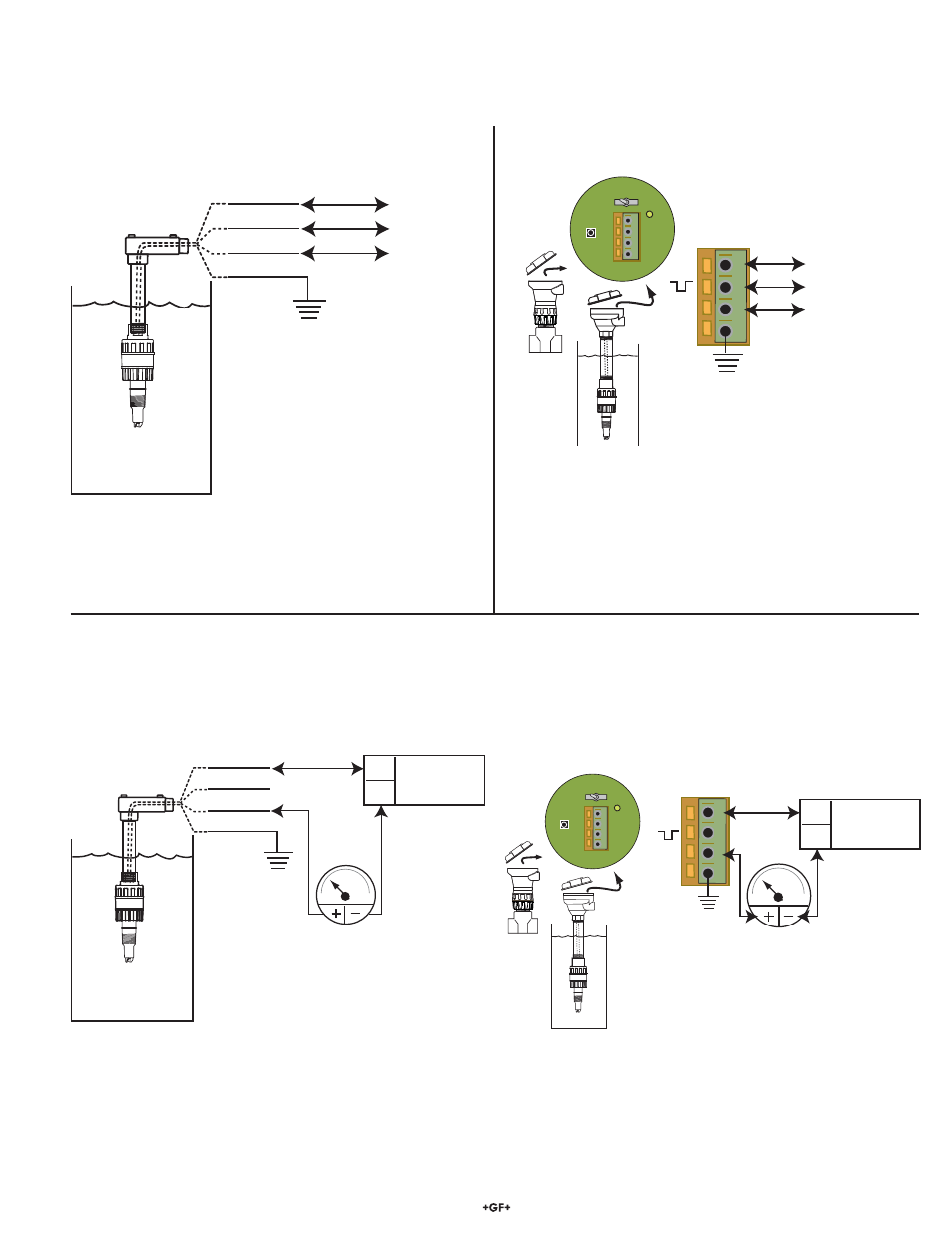
• Connect the 2750 cable directly to a Loop device as shown.
• This
confi guration does not provide any calibration capability
within the 2750 system. Periodic calibration must be
performed at the external equipment.
6. Digital
(S
3
L) wiring
• When the 2750 is powered with 5 VDC, the digital (S
3
L) serial data output is automatically selected.
• S
3
L data is used exclusively by Signet instruments.
• Remove approximately 10 mm (0.4 in.) of insulation and tin each conductor before inserting into connectors.
• Connect the 2750 cable directly to S
3
L I/O terminals.
• 8900 users: If this direct wiring is used, set the CALIBRATE
menu to "perform calibration at INSTRUMENT"
• When the 2750 includes a terminal block, connect the 2750
terminals as shown to any S
3
L I/O port.
• 8900 users: If the 2750 includes the EasyCal accessory,
set the CALIBRATE menu to "perform Calibration at either
SENSOR or INSTRUMENT"
• If SENSOR, use standard pH buffer values (pH 4, 7, or 10) to
perform periodic calibration.
• If INSTRUMENT, any pH value can be used.
• When the 2750 includes a terminal block, connect the 2750
terminals to the Loop device as shown.
• If the 2750 includes the EasyCal accessory, use standard pH
buffer values (pH 4, 7, or 10) to perform periodic calibration.
7. 4 to 20 mA Loop wiring
• When the 2750 is powered with 12 to 24 VDC, the 4 to 20 mA loop output is automatically selected.
• Remove approximately 10 mm (0.4 in.) of insulation and tin each conductor before inserting into connectors.
Current Loop with no junction box
Current loop with Junction box
S
3
L with no junction box
S
3
L with Junction box
Optional
Earth ground
1
2
3
4
+5 VDC
S
3
L data
Signal Ground
+
S
-
SW2
Run
Cal
SW1
D1
1
2
3
4
1
2
3
4
4 to 20 mA loop
monitor
Optional
Earth Ground
Power Supply
DC 12 to 24 V
+
-
+
S
-
SW2
Run
Cal
SW1
D1
1
2
3
4
4 20
4 to 20 mA loop
monitor
Optional
Earth Ground
Power Supply
DC 12 to 24 V
+
-
Black
Red (no connection)
White
Shield
4
20
+5 VDC
S
3
L data
Signal Ground
Black
Red
White
Shield