1 system power/loop connections, Enter a b a, Enter – GF Signet 8550 ProcessPro Flow Transmitter User Manual
Page 3
3
Signet 8550-3 Flow Transmitter Instructions
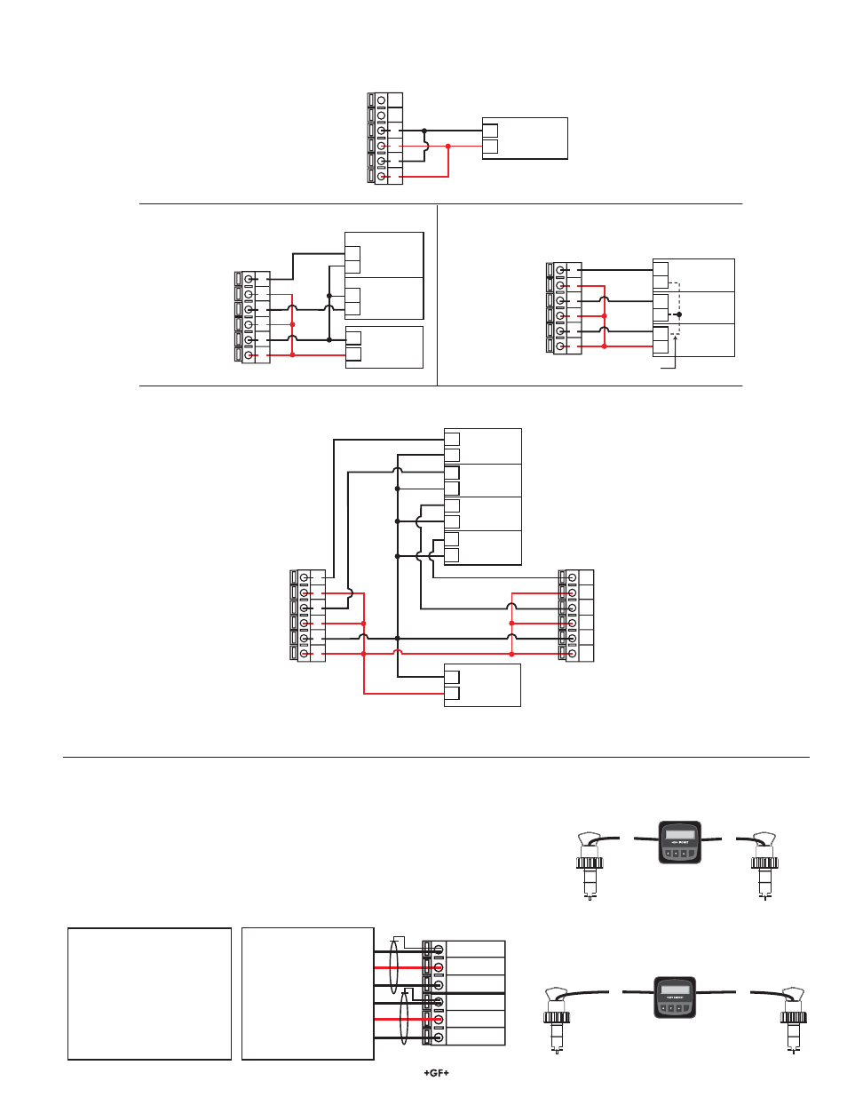
3.1 System Power/Loop Connections
Snsr 2 Gnd
(SHIELD)
Snsr 2 IN
(RED)
Snsr 2 V+
(BLACK)
Snsr 1 Gnd
(SHIELD)
Snsr 1 IN
(RED)
Snsr 1 V+
(BLACK)
16
15
14
13
12
11
Terminals
No Aux Power
515/3-8510-XX
525
2100
2536/3-8512-XX
2540/2541
Aux Power Required
2000
2507
2551
2552
Open-collector input signals
Maximum cable length is 60 m (200 ft.)
for 515/8510-XX, 525 and any sinusoidal
fl ow signal.
Maximum cable length is 305 m (1000 ft).
for 2536/8512-XX, 2540/2541 and any
open-collector fl ow signal.
Flow
Flow1: 6.25 GPM
Flow2: 9.75 GPM
ENTER
A
B
A
200 ft. (60 m)
B
200 ft. (60 m)
3.2 Sensor Input Connections
Wiring Tips:
• Do not route sensor cable in conduit containing AC power wiring. Electrical
noise may interfere with sensor signal.
• Routing sensor cable in grounded metal conduit will help prevent electrical
noise and mechanical damage.
• Seal cable entry points to prevent moisture damage.
• Only one wire should be inserted into a terminal. Splice double wires outside
the terminal.
8550 3
Flow
Flow1: 6.25 GPM
Flow2: 9.75 GPM
ENTER
A
B
A
1000 ft. (300 m)
B
1000 ft. (300 m)
–
+
6
5
4
3
2
1
6
5
4
3
2
1
6
5
4
3
2
1
6
5
4
3
2
1
–
+
+
–
+
–
–
+
+
–
–
+
+
–
+
–
–
+
6
5
4
3
2
1
+
–
+
–
NC
NC
Loop 2 –
Loop 2 +
System Power/Loop 1 –
System Power/Loop 1 +
AUX Power –
AUX Power +
Loop 2 –
Loop 2 +
System Power/Loop 1 –
System Power/Loop 1 +
AUX Power –
AUX Power +
4-20 mA in
4-20 mA in
4-20 mA in
4-20 mA in
Channel 3
Channel 4
Channel 1
Channel 2
Loop 2 –
Loop 2 +
System Power/Loop 1 –
System Power/Loop 1 +
AUX Power –
AUX Power +
Channel 2
4-20 mA
Channel 1
4-20 mA
Channel 2
4-20 mA
Channel 1
4-20 mA
Loop 2 –
Loop 2 +
System Power/Loop 1 –
System Power/Loop 1 +
AUX Power –
AUX Power +
Loop 2 –
Loop 2 +
System Power/Loop 1 –
System Power/Loop 1 +
AUX Power –
AUX Power +
Auxiliary Power Note:
Auxiliary power is necessary for flow sensors that require more than 1.5 mA of current.
This includes the following Signet flow sensors: 2000, 2507, 2551, 2552 and all Open Collector signal inputs.
Power
Supply
12-24 VDC
Example: Two transmitters connected to PLC/Recorder with separate power supply
Internal
PLC Connection
Power
Supply
12-24 VDC
Transmitter
Terminals
Connection to a PLC with built-in power supply
Power
Supply
12-24 VDC
Connection to a PLC/Recorder, separate supply
PLC or Recorder
Transmitter
Terminals
Power
Supply
12-24 VDC
Stand-alone application, no current loop used
Transmitter
Terminals
PLC Terminals
PLC or Recorder
Transmitter 1
Terminals
Transmitter 2
Terminals