Changing the valves, Changing the valves 19.3 – Burkert Type 8681 User Manual
Page 83
83
Replacement of Components and Modules
installation procedure:
Carefully insert the entire electronics module into the recess in the lower housing part.
→
Plug the electronics module carefully onto the contact pins for the position measuring system.
→
Refasten the electronics module with the Torx T10 screw (torque 0.4 Nm).
→
Reattach the electrical connections.
→
Check DIP switch positions (4-switch block for color coding, 8-switch block on DeviceNet electronics module
→
for address and Baud rate) and set the previously noted switch settings, if necessary.
If necessary, set AS interface address and jumper positions.
→
Perform Teach-In process (see chapter
→
15.1. Setting the Position Measuring System (Teach-In)).
Be sure to work carefully and cautiously, so that the electronics are not damaged.
Close the housing observing the notes contained in chapter "
→
8. Opening and Closing the Housing".
Changing the Valves
19.3.
According to the design, zero to three valve modules have been installed in the control head. The valves have
been designed with the flow restriction equipment for intake and exhaust air and must be installed as a valve
module.
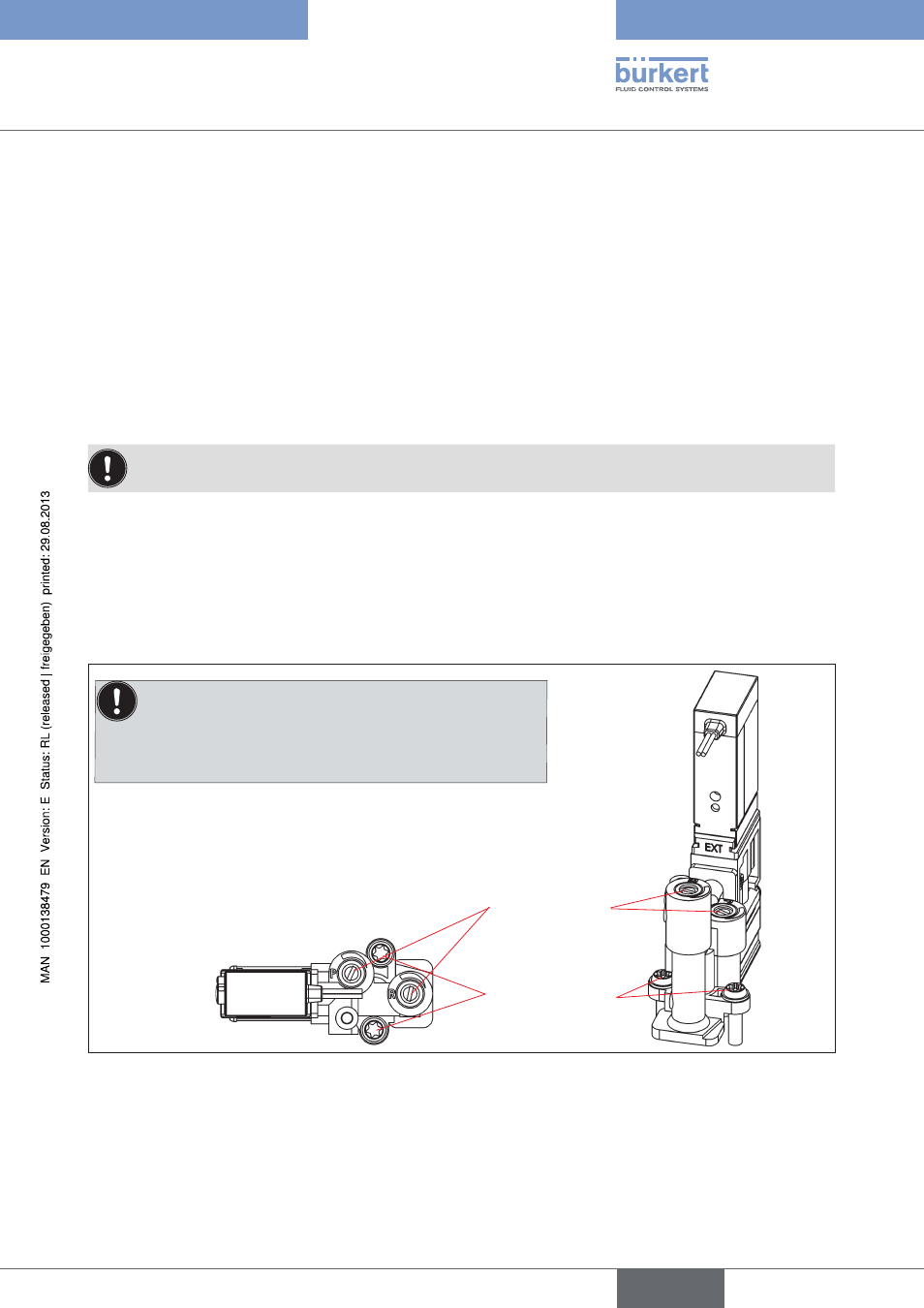
Valve module from above
Flow restriction
screws
Torx screws (T10),
tightening torque:
1 Nm
note:
Disassemble/assemble the valves in upright position as there is
otherwise a risk that the non-return valve falls out!
Valve module
Fig. 32:
procedure:
Open the housing observing the notes contained in chapter "
→
8. Opening and Closing the Housing".
If necessary, mark the electrical connections to ensure correct assignment during reinstallation.
→
english
Control Head Type 8681