Burkert Type 8681 User Manual
Page 64
64
120 V AC - Design
Danger!
risk of electric shock if the pe connection is not connected!
the PE connection must be connected!
•
Clamp the protective conductor to the PE connection.
→
Check correct grounding.
→
Close the housing observing the notes contained in chapter "
→
8. Opening and Closing the Housing".
note!
ensure ip protection!
To ensure IP protection, the union nuts of the cable glands must be tightened in accordance with the cable
•
sizes or dummy plugs used (approx. 1.5 Nm).
If an external initiator is not used, the cable gland (wrench size 19, Ø 3 - 6 mm) must be tightly sealed with
•
the dummy plug (Ø 5 - 6 mm) supplied from the factory!
note!
use of the control head in explosive atmosphere
Only use cables and cable glands that are allowed for the respective application area, and mount the cable
•
gland according to the respective operating instructions!
Close all unnecessary openings with lock screws/plugs approved for explosions area!
•
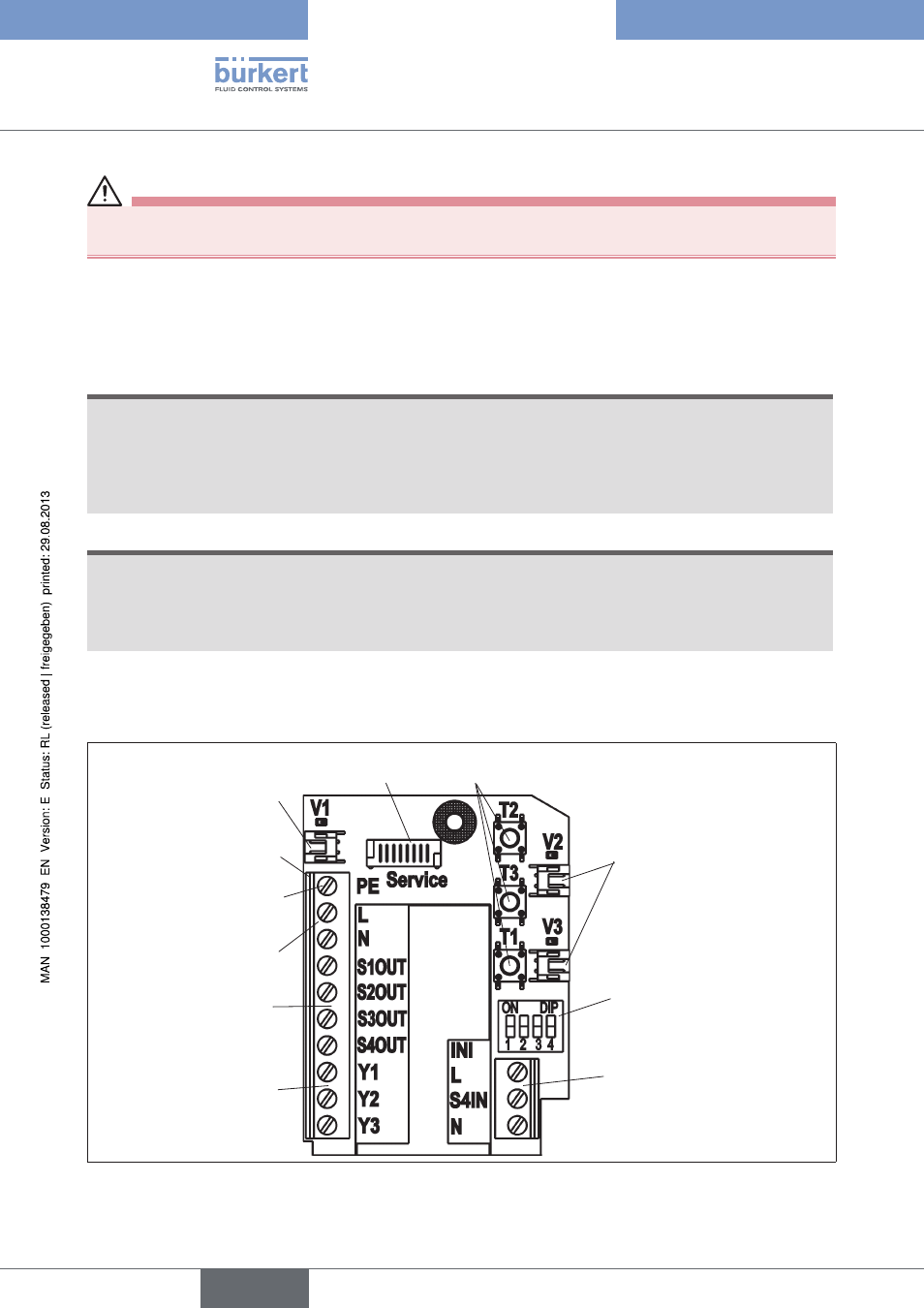
120 V aC electronics Module, terminal Strip Configuration:
Solenoid valve
connection with
status
LED for Valve 1
Terminal strip
Protective
conductor
(protection earth)
Power supply
(L/N)
Service inter-
face
DIP switches for
color coding the
LEDs
Connection
for the exter-
nal initiator
Feedback
signals
S1-S4 OUT
Control sole-
noid valves
Y1-3
Teach-In buttons
T1-3
Solenoid valve con-
nection with status
LEDs for Valves 2
& 3
120 V AC electronics module
Fig. 25:
english
Control Head Type 8681