24 v dc - design, Electrical connection options, Electrical data – Burkert Type 8681 User Manual
Page 31: Hapter, Electrical connection options 10.1, Electrical data 10.2
31
24 V DC - Design
10.
24 V dC - design
electrical connection options
10.1.
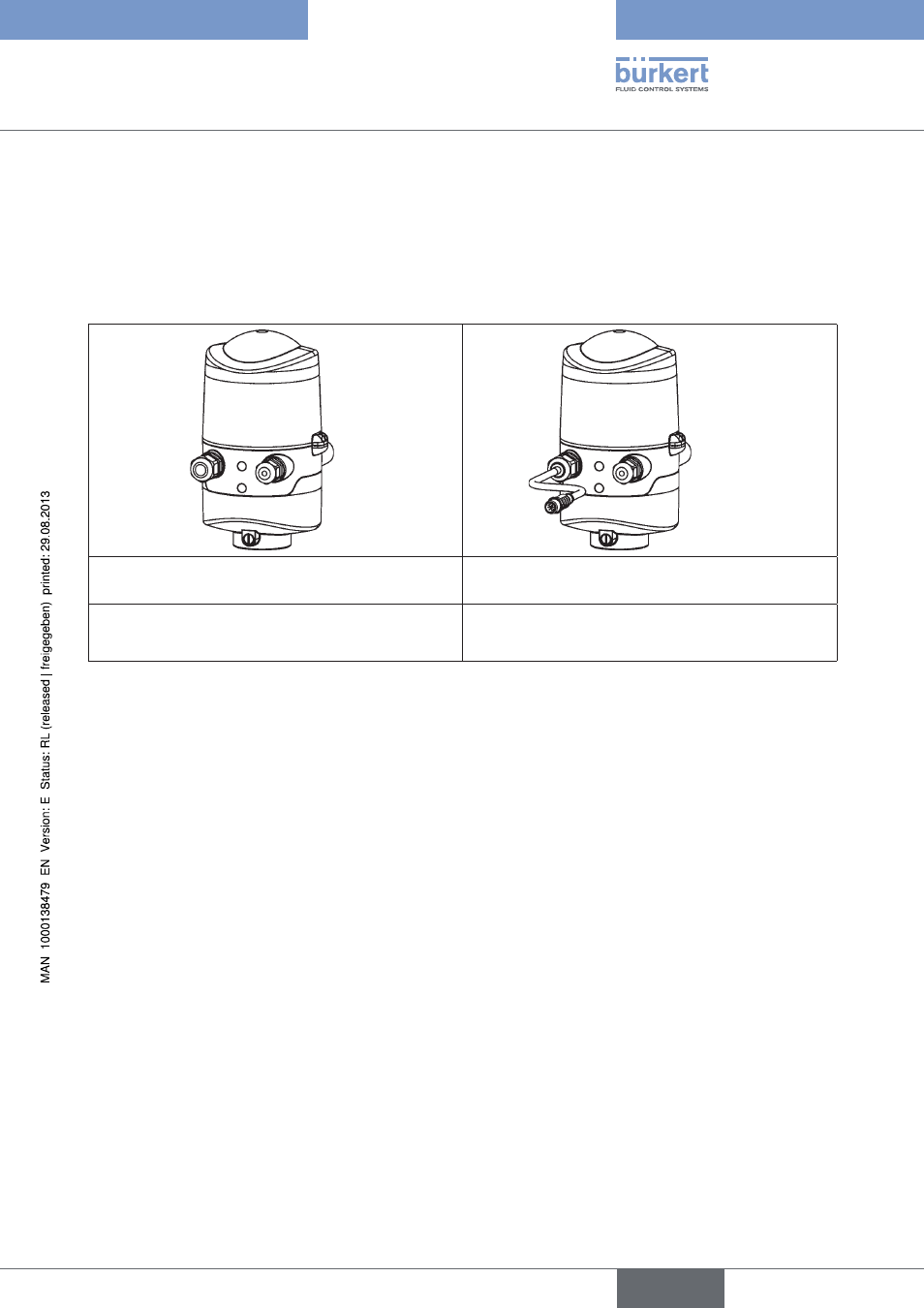
The following connection concepts are available for the electrical connection of the control head:
Cable gland
Cable gland with multi-pole connection
(M12 plug according to IEC 61076-2-101, 12-pole)
Connection left: Voltage, signals
Connection right: external initiator
Connection left:
Voltage, signals
Connection right: external initiator
Connection Concepts 24 V DC
Fig. 10:
electrical data
10.2.
power supply:
12 ... 28 V DC, residual ripple 10 %
connections:
Cable gland version
1 x M16 x 1.5 cable gland / A/F22
for power supply and signals
clamping area 5 to 10 mm, with dummy plugs
with screw terminals for cable cross-sections of 0.14 to 1.5 mm
2
1 x M16 x 1.5 cable gland / A/F19
for external initiator
clamping area 3 to 6 mm, with dummy plugs
with screw terminals for cable cross-sections 0.14 to 1.5 mm²
Multi-pole connection version
1 x M16 x 1.5 cable gland / A/F22 with multi-pole connection
(M12 plug according to IEC 61076-2-101, 12-pole on a cable of
8 cm length for power supply and signal)
1 x M16 x 1.5 cable gland / A/F19
for external initiator
clamping area 3 to 6 mm, with dummy plugs
with screw terminals for cable cross-sections 0.14 to 1.5 mm²
power consumption (standby current): 30 mA at 24 V DC
english
Control Head Type 8681