Network topology of a devicenet system, Configuring the devicenet address / baud rate, Network topology of a devicenet system 12.9 – Burkert Type 8681 User Manual
Page 53
53
DeviceNet - Design
network Topology of a devicenet system
12.9.
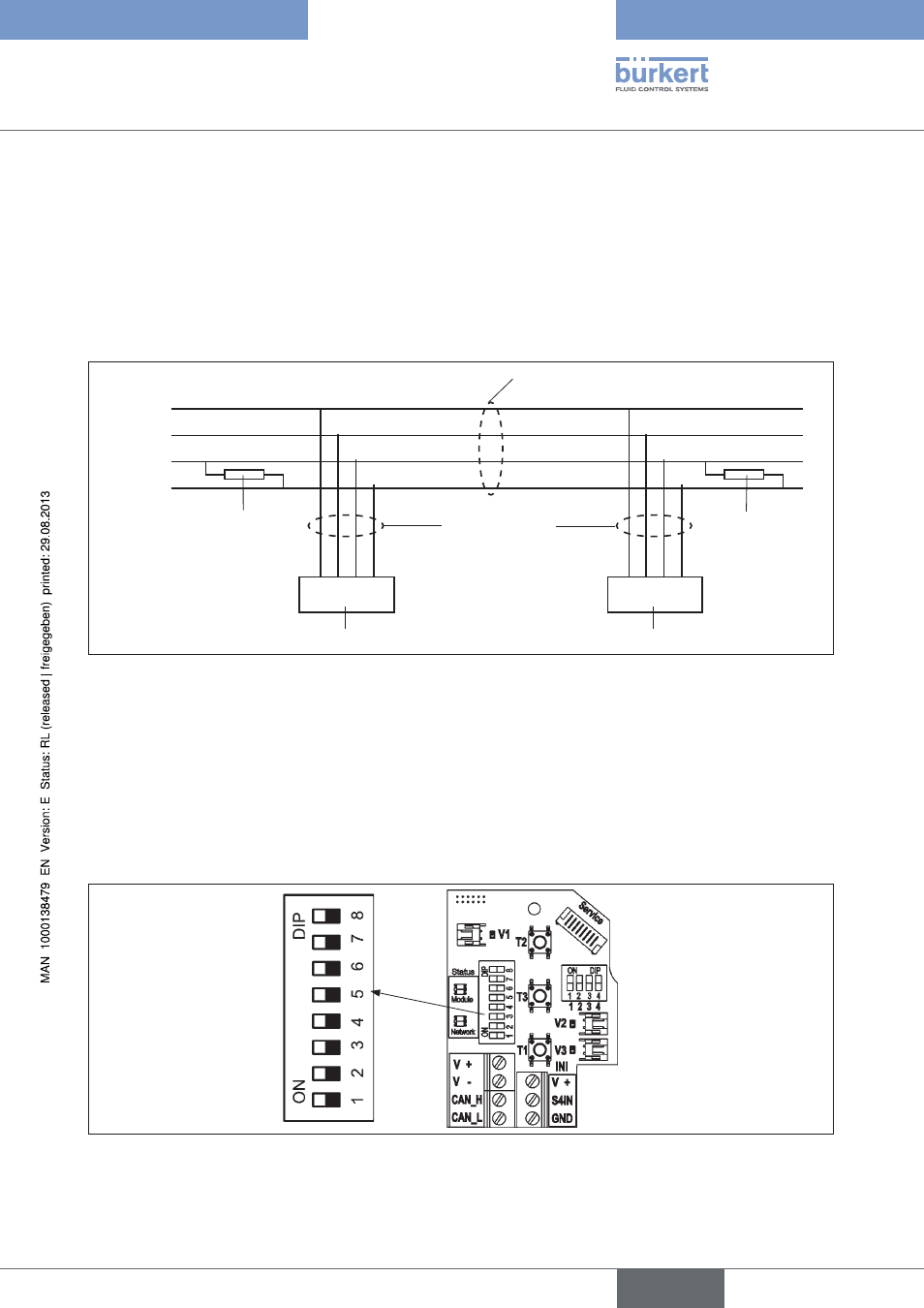
When installing a DeviceNet system, ensure that the terminating circuit of the data lines is correct. The circuit pre-
vents the occurrence of interference caused by signals reflected onto the data lines.
The trunk line must be terminated at both ends with resistors of 120Ω and 1/4 W power loss (see "
Fig. 21:
Network topology").
Fig. 21: illustrates a line with one trunk line and several drop lines. Trunk lines and drop lines consist of identical
material.
Trunk line
DeviceNet cable
Terminating
resistor
120 Ω
¼ W
Terminating
resistor
120 Ω
¼ W
Drop lines
DeviceNet cable,
max. 6 m long
t01
tn
Subscriber 1 (node 1)
Subscriber n (node n)
V +
V –
CAN_H
CAN_L
Network topology
Fig. 21:
Configuring the devicenet address / baud rate
12.10.
8 DIP switches are available for configuration:
DIP switches 1 to 6
for the DeviceNet address
•
DIP switches 7 to 8
for the baud rate
•
Position of the DIP switches
Fig. 22:
english
Control Head Type 8681