Setting the color combinations, Blinking pattern & fault signaling, Setting the color combinations 16.1 – Burkert Type 8681 User Manual
Page 73
73
LED - Color Assignments
setting the Color Combinations
16.1.
setting of the possible color combinations with the help of the dip switches:
S1
S2
S3
S4
Fault
DiP1
DiP2
DiP3
DiP4
green
yellow
green
red
0
0
0
0
yellow
green
yellow
red
1
0
0
0
green
red
green
yellow
0
1
0
0
red
green
red
yellow
1
1
0
0
green
yellow
yellow
red
0
0
1
0
yellow
green
green
red
1
0
1
0
green
red
red
yellow
0
1
1
0
red
green
green
yellow
1
1
1
0
green
yellow
green
green
red
0
0
0
1
yellow
green
yellow
yellow
red
1
0
0
1
green
red
green
green
yellow
0
1
0
1
red
green
red
red
yellow
1
1
0
1
green
yellow
yellow
yellow
red
0
0
1
1
yellow
green
green
green
red
1
0
1
1
green
red
red
red
yellow
0
1
1
1
red
green
green
green
yellow
1
1
1
1
(S4IN may be a normally closed contact (NC) or a normally open contact (NO) - factory setting: NO contact,
it can be changed via the service interface.)
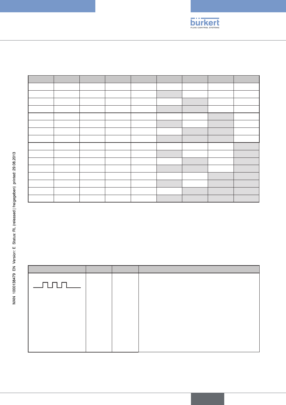
16.2. Blinking pattern & fault signaling
The LEDs blink in different blinking patterns in the event of a fault or in various states.
Blinking patterns
on
oFF
note
100 ms
100 ms
Blinks three times in the corresponding color for that
position:
Teach-In confirmation (after successful teaching:
the color for position 1 and 2 is continuously on)
Blinks three times in the corresponding fault color:
- if target could not be located in the measuring area
during teaching, or
- if teach position is too close (±0.5 mm) to a previously
defined teach position, or
- if magnetic manual control is used, even though manual
control function was disabled by software
english
Control Head Type 8681