Electrical installation as interface – Burkert Type 8681 User Manual
Page 44
44
AS Interface - Design
11.7. electrical installation as interface
Internal cabling work is not required for any of the AS Interface designs with multi-pole connection, which makes
installation and start-up on site considerably easier and quicker, reducing the risk of leaks.
However, you will require the correspondingly assembled cable sets with the following pin assignments. Likewise,
the jumpers on the electronics module must be set correspondingly (see figures below).
note!
use of the control head in explosive atmosphere
Only use cables and cable glands that are allowed for the respective application area, and mount the cable
•
gland according to the respective operating instructions!
Close all unnecessary openings with lock screws/plugs approved for explosions area!
•
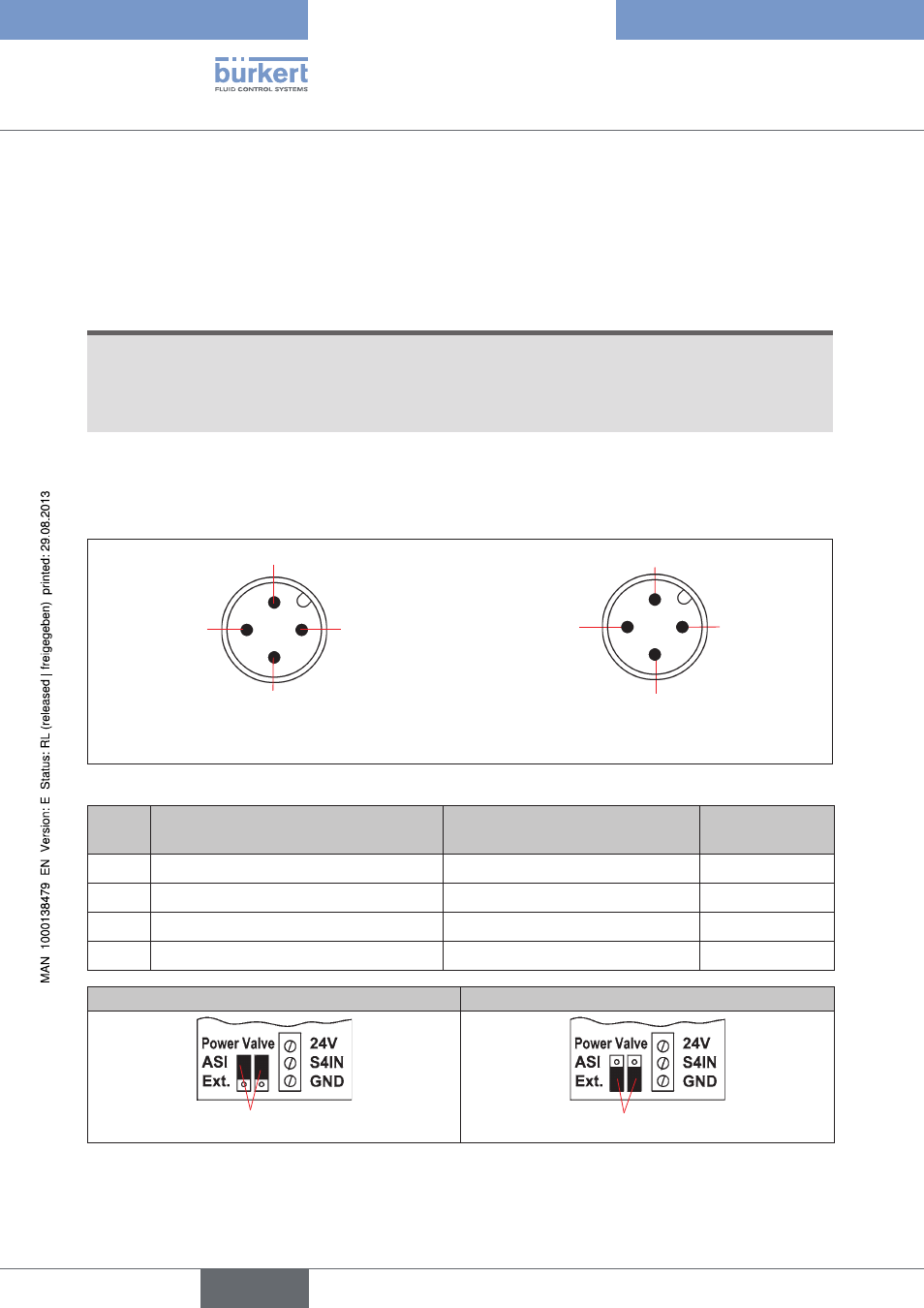
as interface bus connection (power supply via bus or external power supply)
1 4-pole male M12 round plug (acc. to IEC 61076-2-101)
(view onto the M12 plug, from the front onto the pins)
Pin 2: NC
Pin 3: ASI -
Pin 1: ASI +
Pin 4: NC
Bus connection
power supply via bus
Pin 2: GND
Pin 3: ASI -
Pin 1: ASI +
Pin 4: 24 V +
Bus connection
with external power supply
AS Interface bus connection (power supply via bus / external power supply)
Fig. 15:
pin
configuration
(supply via bus)
configuration
(external power supply)
Wire color
1
AS interface, ASI+
AS interface, ASI+
brown
2
not used
GND
white
3
AS interface, ASI -
AS interface, ASI -
blue
4
not used
24 V +
black
Power supply to the valves via the bus
External power supply to the valves
Jumper
Jumper
Jumper setting on AS interface electronics module: Power supply to the valves via the bus or externally
Fig. 16:
english
Control Head Type 8681