Functions / options / designs, Structure of the control head, Functions / options / designs 5.4 – Burkert Type 8681 User Manual
Page 14
14
System Description
short mechanical and pneumatic installation times.
•
For increased safety requirements (e.g. in the explosion-risk area) a seal or a hood safeguard using plastic self-
•
cutting screws (3 mm diameter, approx. 10 mm length; e.g. Ejot PT screws K 30 x 10) are required.
conform to the ATEX Directive 94/9/EC (Dust ATEX category 3D and Gas ATEX category 3G - see chapter
•
functions / Options / designs
5.4.
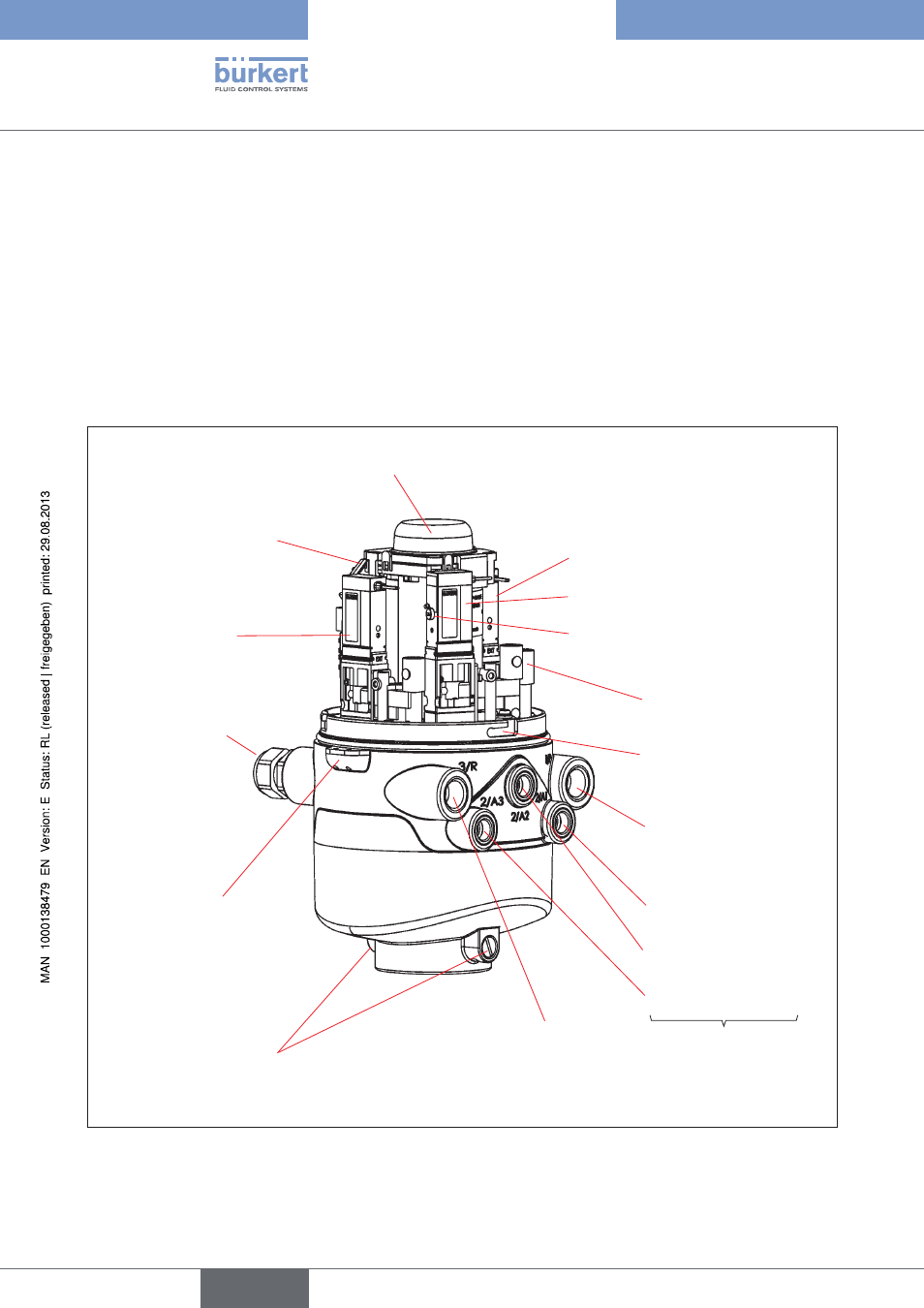
structure of the Control Head
5.4.1.
Electronics module with
connection terminals,
service interface and
Teach-In buttons
(back side)
Solenoid valve 3
Solenoid valve 2
Solenoid valve 1
Cable gland
(back side)
Exhaust air connection (3/R)
Mechanical manual
control (red lever)
Supply pressure
connection(1/P)
Working connections
(2/A1 - 3)
Flow restriction screw(s)
for P and R
(2 per solenoid valve)
Solenoid valve 3 (2/A3)
Solenoid valve 2 (2/A2)
Solenoid valve 1 (2/A1)
Position measuring system
with LED's in three colors
Silencer in the exhaust air
connection (3/R), not shown
Sealing lug
(on lower housing part)
2 locking screws (shoulder
screws M5); no sealing
function, merely as protection
against pulling off from the
hub flange
Locking groove (3x)
Fig. 1:
Structure of Control Head Type 8681
english
Control Head Type 8681