120 v ac - design, Electrical connection options, Electrical data – Burkert Type 8681 User Manual
Page 60: Electrical connection options 13.1, Electrical data 13.2
60
120 V AC - Design
13.
120 V aC - design
electrical connection options
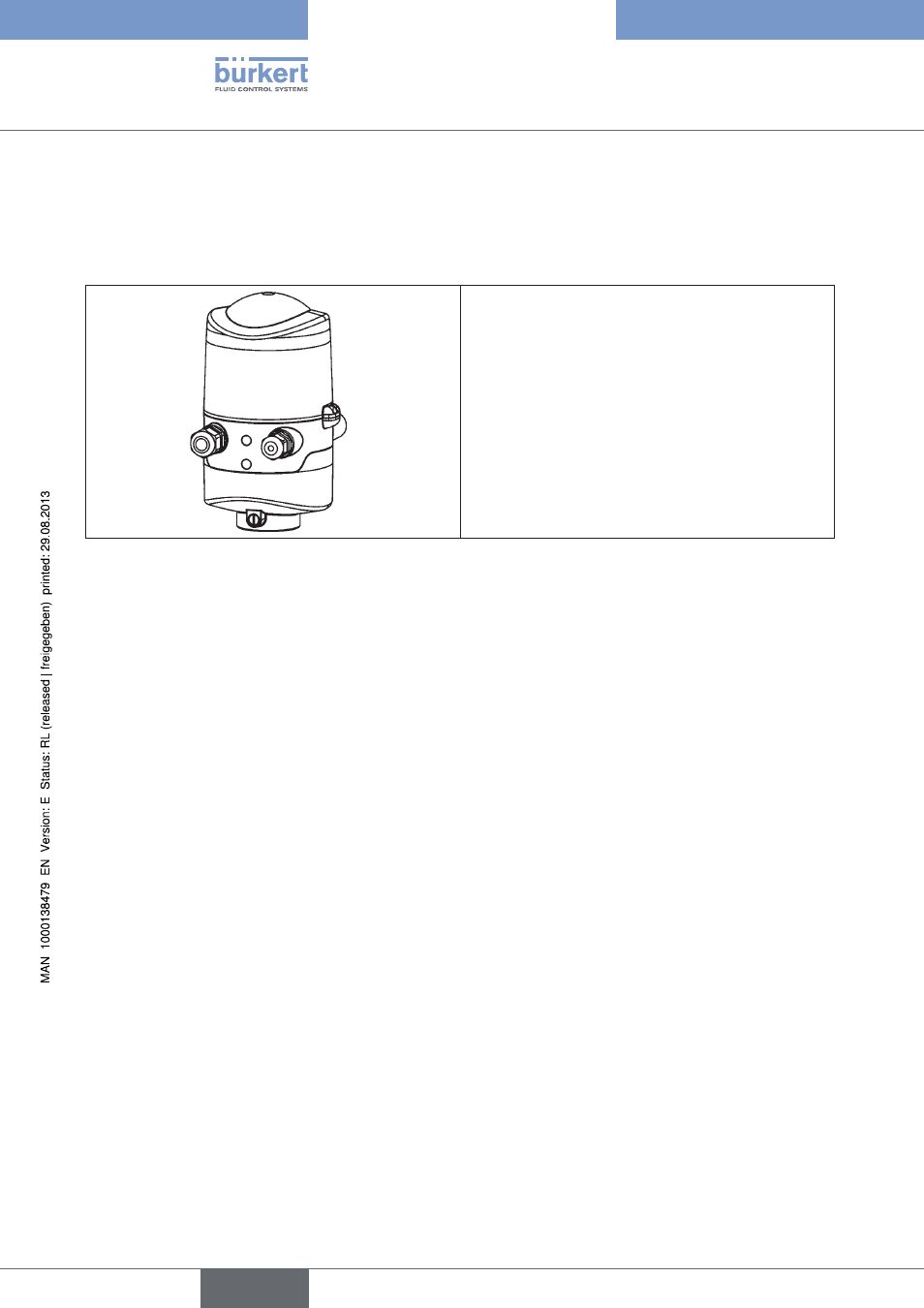
13.1.
Cable gland:
Connection left: Voltage, signals
Connection right: external initiator
Connection concept 120 V AC
Fig. 24:
electrical data
13.2.
central power supply:
110 to 130 V AC, 50/60 Hz
connections: Cable gland
1 x M16 x 1.5 cable gland / SW22
for power supply and signals
clamping area 5 to 10 mm, with dummy plugs
with screwterminals for cable cross-sections of 0.5 to 1.5 mm
2
,
incl. PE connection terminal
(tightening torque of the clamping screws max. 0.5 Nm)
1 x M16 x 1.5 cable gland / SW19
for external initiator
clamping area 3 to 6 mm, with dummy plugs
with screw terminals for cable cross-sections of 0.5 to 1.5 mm²
power consumption (standby current):
10 mA at 120 V AC
solenoid valves:
Power consumption per solenoid valve:
max. 1.4 VA (1.7 VA during activation)
Power consumption per solenoid valve:
12 mA at 120 V AC
Operating mode:
Long-term operation (100 % ED)
central display of the switching states:
13 mA with a power supply of 120 V AC per illuminated
display;
Color switching see chapter
Outputs/binary feedback signals: S1out - S3out
Design:
Normally open contact, L switching,
short-circuit protection via automatically resetting fuse
switchable output current:
max. 50 mA per feedback signal
Output voltage - active:
≥ (operating voltage - 2 V)
Output voltage - inactive:
max. 1 V in unloaded state
english
Control Head Type 8681