Burkert Type 8681 User Manual
Page 24
24
Installation
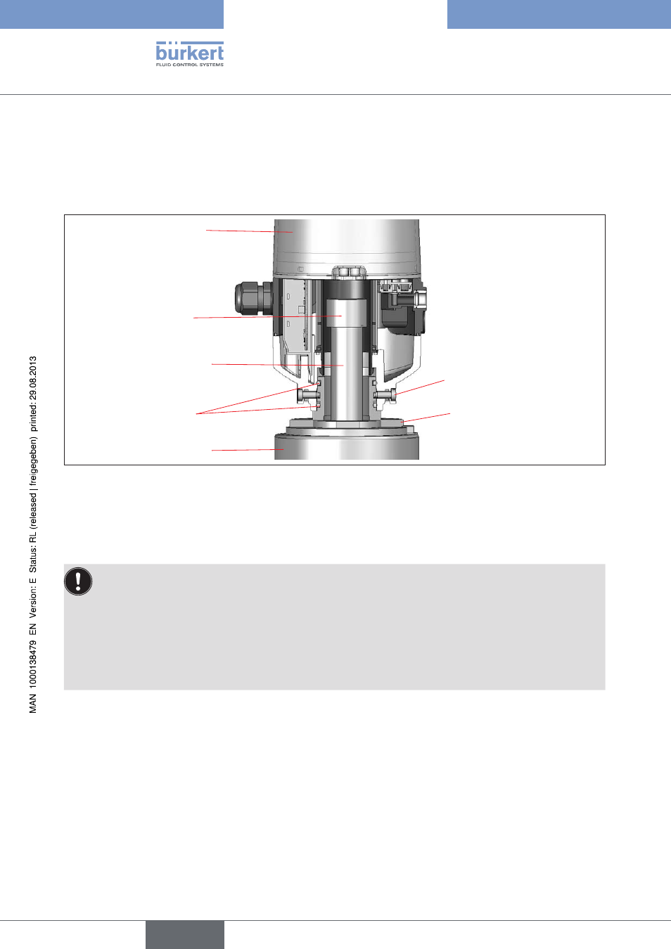
screws M5), which engage in the middle groove of the hub flange (protection against pulling off). The control
head can radially slide into any position in 360° arc, seamlessly.
The hub flange and non ferromagnetic piston rod with the target that is used to record the position must comply
with the specifications with regard to material and stability (see chapter
6.5. Position Measuring System Data.
Control head
Process valve
Target made of
1.4021
Piston rod (*)
(max. Ø 30)
O-rings
Hub flange
Fastening
screws (2x)
Fig. 7:
Dimensional diagram of the control head - process valve adaptation
(*)
The fastening materials for target and piston rod may not be made of material with very good electrical con-
ductivity (e.g. copper, aluminum) or of ferromagnetic material.
Stainless steels such as e.g. 1.4404 are suitable.
To ensure the proper function of the position measuring system, the axial deviation of the adapter must
•
be less than ± 0.1 mm to the spindle when mounted!
Use exclusively Bürkert adaptations.
•
Prior to assembling the control head onto the hub flange, lightly grease the O-rings with a silicone
•
grease (e.g. Paraliq GTE 703).
A seal or a hood safeguard using plastic self-cutting screws is required in the explosion-risk area, so
•
that unintentional opening of the housing will be prevented!
For dimensional relationships, see also chapter
6.5. Position Measuring System Data.
assembly sequence on the example of a double-seated
7.2.2.
Valve
procedure:
Mount the piston rod with the target on the process valve spindle. Observe reference dimensions!
→
Fasten the hub flange on the process valve.
→
During this, observe central alignment and sealing conditions!
english
Control Head Type 8681