Changing the electronics module – Burkert Type 8681 User Manual
Page 82
82
Replacement of Components and Modules
19.2. Changing the electronics Module
note!
electrostatic sensitive components / modules!
The device contains electronic components, which react sensitively to electrostatic discharge (ESD). Contact
•
with electrostatically charged persons or objects may be hazardous to these components. In the worst case
scenario, they will be destroyed immediately or will fail after start-up.
Observe the requirements in accordance with DIN EN 61340-5-1 and 5-2 to minimize or avoid the possibility
•
of damage caused by sudden electrostatic discharge!
Also, ensure that you do not touch electronic components when the power supply voltage is present!
•
removal procedure:
Open the housing observing the notes contained in chapter
→
8. Opening and Closing the Housing.
If necessary, mark the electrical connections to ensure correct assignment during reinstallation.
→
If necessary, note the position of the 4 DIP switches for the set color code and on the DeviceNet electronics
→
module the DIP switches (8-switch block) for Baud rate and address. On the AS-i electronics module, note
the AS interface address and the jumper positions (power supply to AS interface).
Loosen all electrical connections on the electronics module (plug-type connections, screw-type terminal
→
connections).
Loosen the screw-type connection (Torx T10 screw) of the electronics module and store the screw in a safe
→
place.
Carefully press the electronics module forwards so that the contact pins on the position measuring system are
→
exposed.
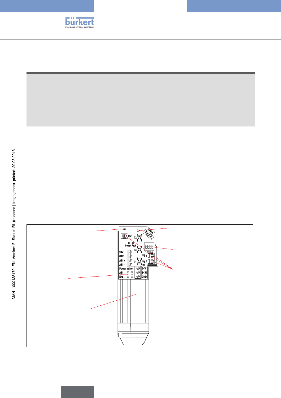
4 DIP switches for
color coding
Fastening screw
(Torx 10)
Connection for the
position measuring
system's contact pins
Electronics module, complete
(sealed lower part,
ready for installation)
Plug-type connections
for valves V1-3
Jumper
for AS interface power supply
Electronics module (example for AS Interface)
Fig. 31:
Carefully lift the electronics module upwards.
→
english
Control Head Type 8681