Burkert Type 8681 User Manual
Page 45
45
AS Interface - Design
The cable with multi-pole connection version is especially suited for direct and flexible connection to the AS interface
cable harness using the ribbon cable terminal (M12 branch circuit, VA branch circuit) that is optionally available.
The optional ribbon cable terminal contacts the AS interface cable harness by means of penetration technology which
allows installation by "clipping in" the AS interface cable harness without cutting and without removing insulation.
Screws
M12 plug-in con-
nector branch circuit
procedure:
Open the ribbon cable terminal
→
(loosen screws and remove cover)
Insert cable harness
→
Close ribbon cable terminal again
→
Tighten the screws
→
Loosen the thread-forming screws slightly and position
them on the existing tapped bore and screw in.
Optional ribbon cable terminal for AS interface cable harness
Fig. 17:
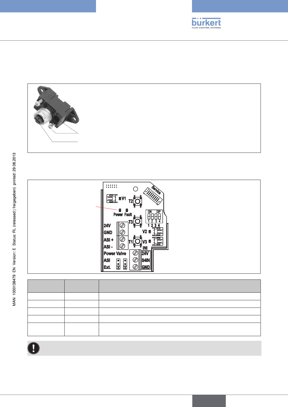
aS interface electronics Module - LeD Status Displays:
LED Status Displays
"Power" and "Fault"
led 1 "power"
(green)
led 2 "fault"
(red)
signalized status
off
off
Power OFF
on
on
No data traffic (expired Watch Dog at slave address does not equal 0)
on
off
OK
flashing
on
Slave address = 0
flashing
flashing
Sensor supply overloaded / manual actuation activated / untaught / mainte-
nance request / smartphone software service mode
The centre illuminated display flashes in the fault color (see chapter
16.2. Blinking Pattern & Fault Signaling)
when Status LED 2 "Fault" is active.
english
Control Head Type 8681