Factory settings in the firmware – Burkert Type 8681 User Manual
Page 22
22
Technical Data
6.6.
factory settings in the firmware
The control head is supplied with the following factory settings of the firmware:
The service interface may only be used in non-explosive atmosphere.
Feedback areas (position measuring system):
(A feedback area is the area, within which a position (e.g. S1) is reported back.)
Signal
Feedback area, top
Feedback area, bottom
Factory setting
[mm]
adjustment range
[mm]
Factory setting
[mm]
adjustment range
[mm]
S1
+ 3.00
+ 10.00 ... + 0.50
- 3.00
- 0.50 ... - 10.00
S2
+ 3.00
+ 10.00 ... + 0.50
- 3.00
- 0.50 ... - 10.00
S3
+ 0.50
+ 10.00 ... + 0.50
- 0.50
- 0.50 ... - 10.00
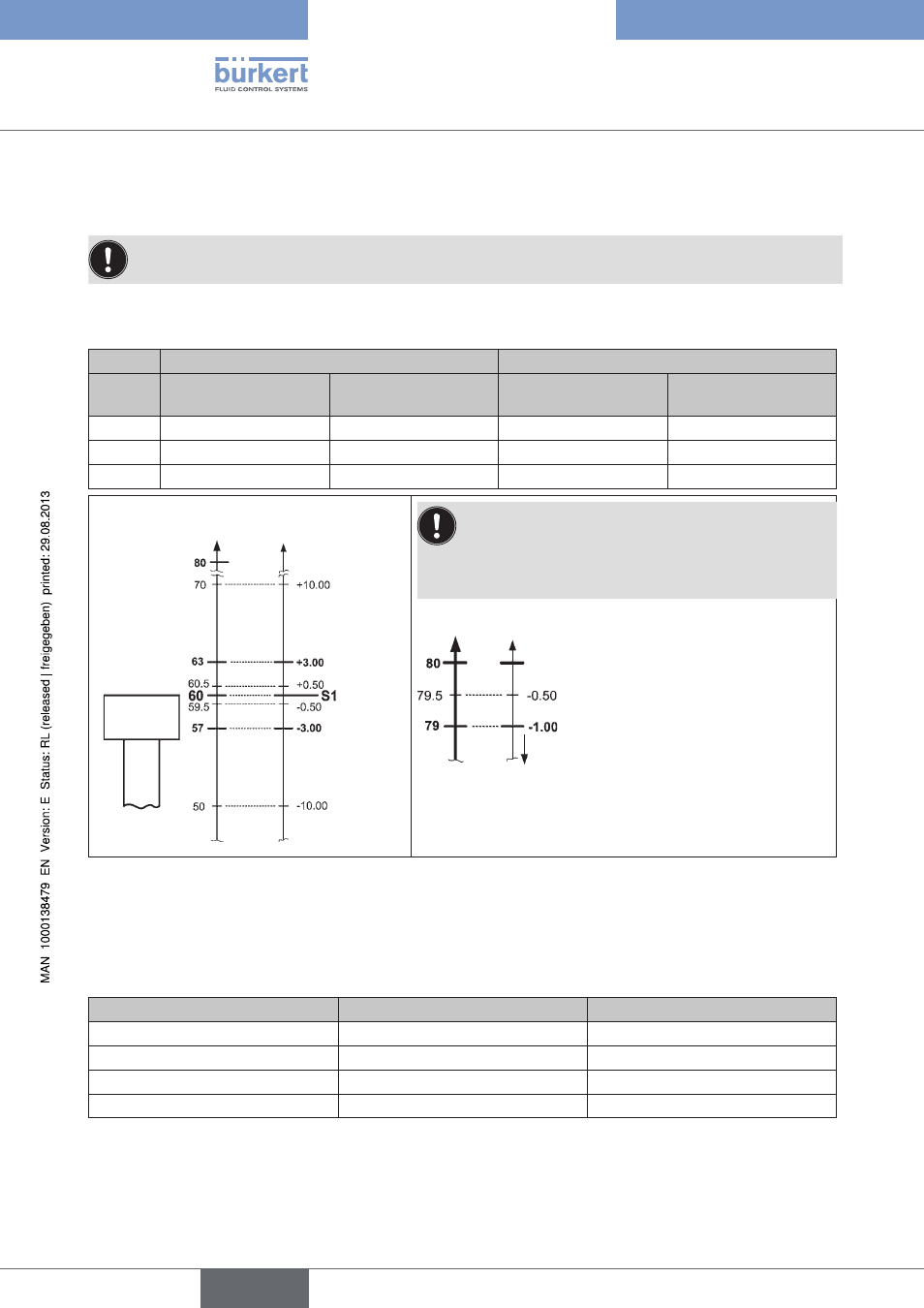
Feedback-
area S1 [mm]
Stroke
[mm]
Target
the feedback area is automatically reduced in the area
of the end positions:
The firmware ensures that a tolerance of at least 1 mm
towards the center position is present in the end
positions.
Exemplary illustration of the upper end position:
upper end position as taught position
(selected feedback area towards
center position)
actual feedback area ensured by
the firmware
Towards center position
Overlaps between S1, S2 and S3 are possible
(see chapter
Schematic diagram (not to scale) of the feedback areas, on the example of Position S1
Fig. 6:
Service function (maintenance request):
The service function is deactivated at the time of delivery. It can be activated via the service interface. Feedback
indicating that service is required (service function) is triggered by the following counter states:
Counter states
Factory setting
adjustment range
Switching cycle counter V1
10,000
(1 ... 255) x 1000
Switching cycle counter V2
50,000
(1 ... 255) x 1000
Switching cycle counter V3
50,000
(1 ... 255) x 1000
Operating duration
365 days
1 ... 65,535 days
Manual control function (magnetic)
- Factory setting: active
It can be deactivated via the service interface.
english
Control Head Type 8681