Burkert Type 8611 User Manual
Page 18
18
ElectricalInstallation
8.1.2. Pin assignment
Circular plug-in connector M12, 8-pole
A straight connector (female) is recommended for the con-
necting cable as the orientation of the connector may vary.
Connector
diagram
Pin
Color Configuration
5
4
3
2
1
8
7
6
1
white
24 V DC power supply
2 (
DIN2) brown Binary input (B_IN)
3
green GND – Power supply,
binary input, binary output
4 (
AOUT) yellow 4 - 20 mA or 0 - 10 V analog
output
(process value or manipulated
variable for valve)
5 (
AIN2) grey
4 - 20 mA or 0 - 10 V analog
input (set-point value / ratio)
6
pink
GND – Analog output
7
blue
GND – Analog input
(set-point value / ratio)
8
(BO1)
red
(+) Binary output (
B_O1)
Tab. 5: Configuration of circular plug-in connector M12, 8-pole
Wire colors when using standard cables (e.g. from
Lumberg, Escha)
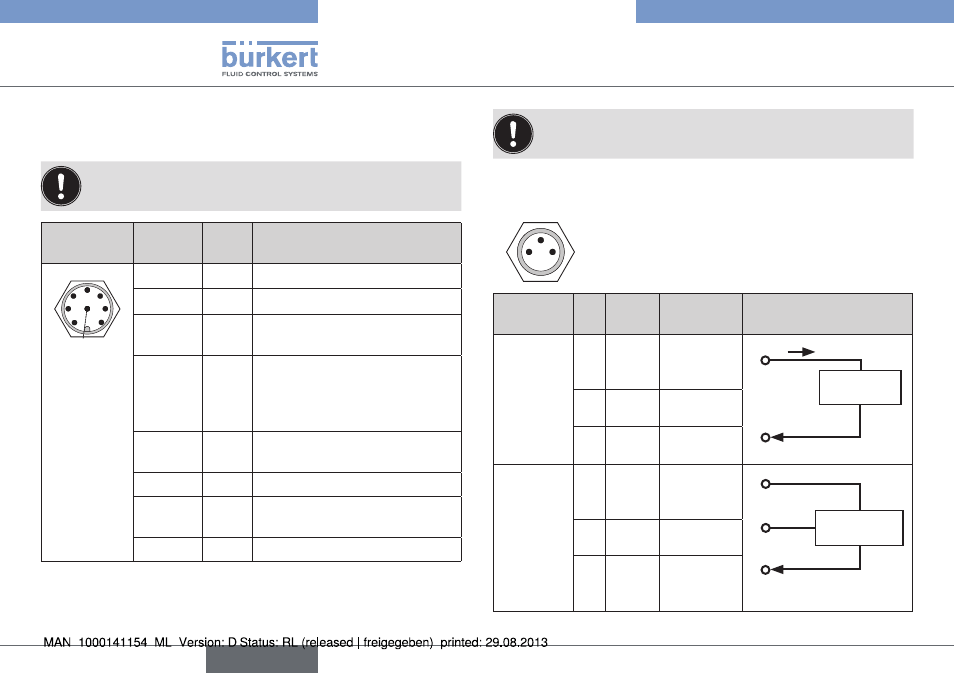
8.1.3. sensor connection
Circular plug-in connector M8, 3-pole
4
3
1
input
signal
Pin Color
Configu-
ration
external circuit
4 - 20 mA
2-wire
supply of
Type 8611
(
AIN1)
1
brown
+ 24 V
sensor
supply
Transmitter
4 - 20 mA
1
4
I
24 V DC
3
blue
not
connected
4
black
Signal input
(source)
4 - 20 mA
/ 0 - 10 V
3-wire
supply of
Type 8611
(
AIN1)
1
brown
+ 24 V
sensor
supply
Transmitter
1 24 V DC
GND
3
4 - 20 mA /
0 - 10 V
4
3
blue
GND
4
black
Signal input
(source)
english
Type 8611