Marlin input description, Marlin input block diagram – ALLIED Vision Technologies Oscar F-810 User Manual
Page 77
Camera interfaces
FireWire Hardware Installation Guide V8.0.0
77
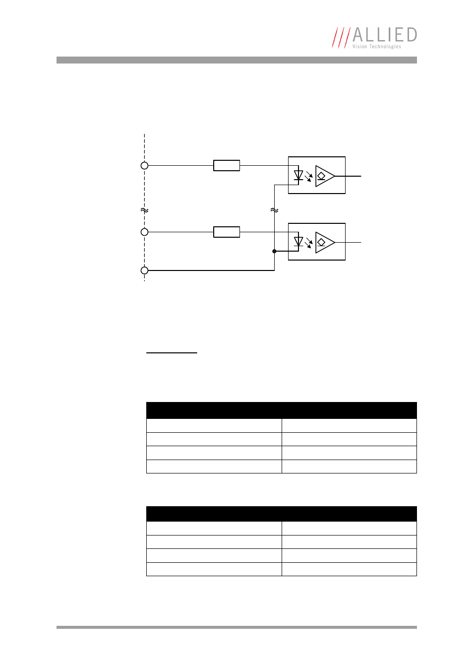
Marlin input description
Marlin input block diagram
The inputs can be connected directly to +5 V. If a higher voltage is used, an
external resistor must be placed in series.
Figure 41: Marlin: input block diagram
Caution
Marlin
Voltages above +36 V may damage the camera.
Used input voltage (U
inVCC
)
External series resistor
5 V
none
12 V
0.82 k
24 V
2.2 k
36 V
3.3 k
Table 18: Marlin: external resistors for voltages higher than 5 V
Parameter
Value
Initial on-current
5 mA
Flux voltage of the LED (@ 10 mA)
1.5 V
Maximum off-current
0.25 mA
Maximum input current
15 mA
Table 19: Marlin: input parameters
GPIn1
InGND
external internal
GPInX
This manual is related to the following products:
- Oscar F-510 Oscar F-320 Marlin F-201 Marlin F-146 Marlin F-145 Marlin F-080 Marlin F-046 Marlin F-033 Guppy F-503 Guppy F-146 Guppy F-080 Guppy F-046 Guppy F-044 Guppy F-038 Guppy F-036 Guppy F-033 Pike F-1600 Pike F-1100 Pike F-505 Pike F-421 Pike F-210 Pike F-145 Pike F-100 Pike F-032 Stingray F-504 Stingray F-201 Stingray F-146 Stingray F-145 Stingray F-125 Stingray F-080 Stingray F-033 Guppy PRO F-503 Guppy PRO F-201 Guppy PRO F-146 Guppy PRO F-125 Guppy PRO F-095 Guppy PRO F-046 Guppy PRO F-033 Guppy PRO F-032 Guppy PRO F-031