Stingray input description, Stingray input block diagram – ALLIED Vision Technologies Oscar F-810 User Manual
Page 48
Camera interfaces
FireWire Hardware Installation Guide V8.0.0
48
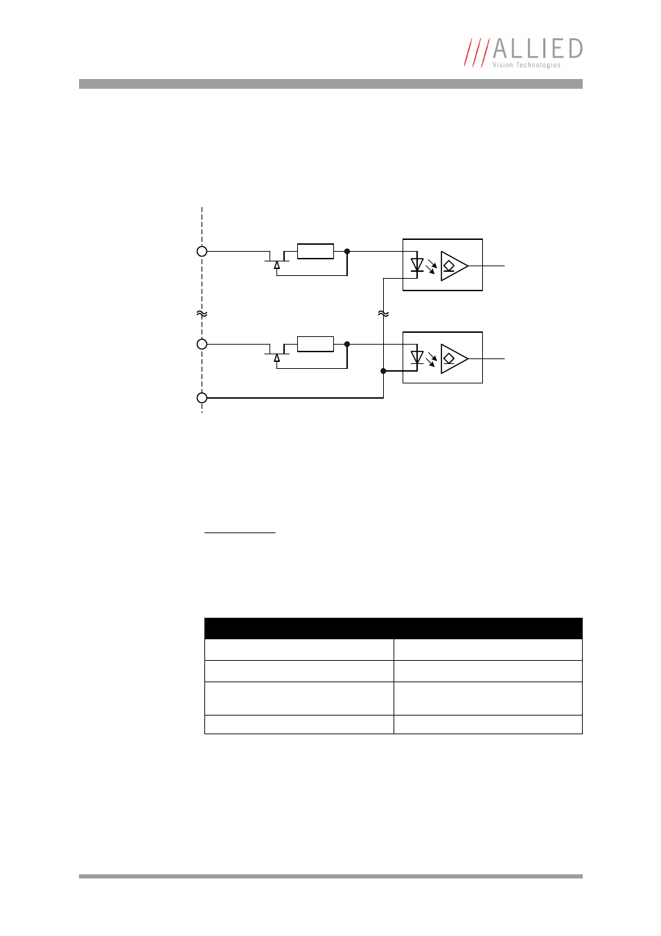
Stingray input description
Stingray input block diagram
The inputs can be connected directly up to max. +24 V. If you want to use volt-
ages from +24 V...+36 V you have to place an external resistor of 1.5 k
(1/10
watt) in series with your voltage source.
Figure 17: Stingray input block diagram
Caution
Stingray
•
Voltages above +24 V (without external resistor) may
damage the camera.
•
Voltages above +36 V (with an external resistor of
1.5 k
may damage the camera.
Parameter
Value
U
in
(low)
0 V ... 1.5 V
U
in
(high)
3 V ... 24 V
Current (constant current source
within the camera)
8 mA
Flux voltage of the LED (@ 10 mA)
1.5 V
Table 8: Stingray input parameters
GPIn1
InGND
external internal
GPInX
This manual is related to the following products:
- Oscar F-510 Oscar F-320 Marlin F-201 Marlin F-146 Marlin F-145 Marlin F-080 Marlin F-046 Marlin F-033 Guppy F-503 Guppy F-146 Guppy F-080 Guppy F-046 Guppy F-044 Guppy F-038 Guppy F-036 Guppy F-033 Pike F-1600 Pike F-1100 Pike F-505 Pike F-421 Pike F-210 Pike F-145 Pike F-100 Pike F-032 Stingray F-504 Stingray F-201 Stingray F-146 Stingray F-145 Stingray F-125 Stingray F-080 Stingray F-033 Guppy PRO F-503 Guppy PRO F-201 Guppy PRO F-146 Guppy PRO F-125 Guppy PRO F-095 Guppy PRO F-046 Guppy PRO F-033 Guppy PRO F-032 Guppy PRO F-031