2 adjacent channel leakage power measurement Page 49: Eakage, Ower, Easurement
Page 49: Eakage, Ower, Easurement
43
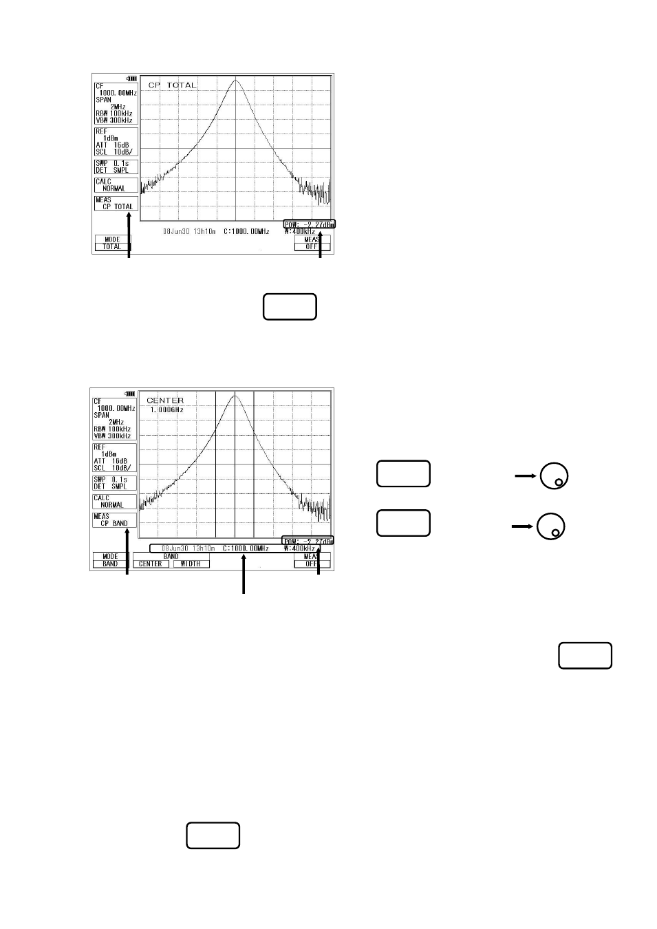
• BAND mode [ By pushing
(MODE), BAND mode is selected.]
The sum of power in the band specified by band center and bandwidth is measured.
19.2 Adjacent Channel Leakage Power Measurement
The adjacent channel leakage power is measured as the ratio of power in the range specified by offset frequency
and bandwidth to carrier power. Both leakage power at the upper and lower side are measured.
Furthermore, the method for measurement is selected out of three methods based on the classification of definition
of carrier power; total power method, reference level method and in-band method.
• Mode selection and measurement
[ By pushing (MODE), TOTAL, BAND or PEAK mode is selected.]
* “ACP TOTAL”, “ACP BAND” or “ACP PK” is displayed in MEAS area on the screen.
* “CP BAND” is displayed in MEAS area on the screen.
* The measured value and the setting parameter are
displayed at the lower part of the screen.
1. By (BAND ENTER) ,
the band center is set.
2. By
(BAND WIDTH) ,
the band width is set.
[Measuring Mode]
[Measured Value]
[Setting parameter]
F2
F3
* “CP TOTAL” is displayed in MEAS area on the screen.
* The measured value is displayed at the lower right corner on
the screen.
[Measuring Mode]
[Measured Value]
F1
F1
F2