6 setting of input impedance, 7 reference level setting range for each unit, Etting of – B&K Precision 2658A - Manual User Manual
Page 32: Nput, Mpedance, Eference, Evel, Etting, Ange for
26
* If the unit is changed to
dBμV, dBmV, dBV or dBm, the offset is automatically changed.
2. By pushing
, the step size of offset is changed. (10 dB, 1 dB, 0.1 dB)
9.6 Setting of Input Impedance
By pushing , the input compensation can be set to 50
Ω (no offset) or 75 Ω. (5.6 dB offset
compensation)
The reference level is adjusted automatically, based on the input impedance selection. When the input impedance
is set to 75
Ω, the reference level is displayed including offset and conversion of 75Ω. For the amplitude reading to
be correct, a coaxial
50 Ω /75 Ω impedance conversion adapter must be connected to the RF input.
* When “75
Ω” is selected, values in Amplitude axis setting values display area will change according to
75
Ω, and the offset is set to 5.7 dB (insertion loss of 50 Ω /75 Ω adapter ). Moreover, the offset can be
changed.
When the unit at marker point is set to W, V, V/m or other, it is converted correctly from dBm.
* Be sure to attach a coaxial
50 Ω /75 Ω impedance conversion adapter when selecting “75 Ω”
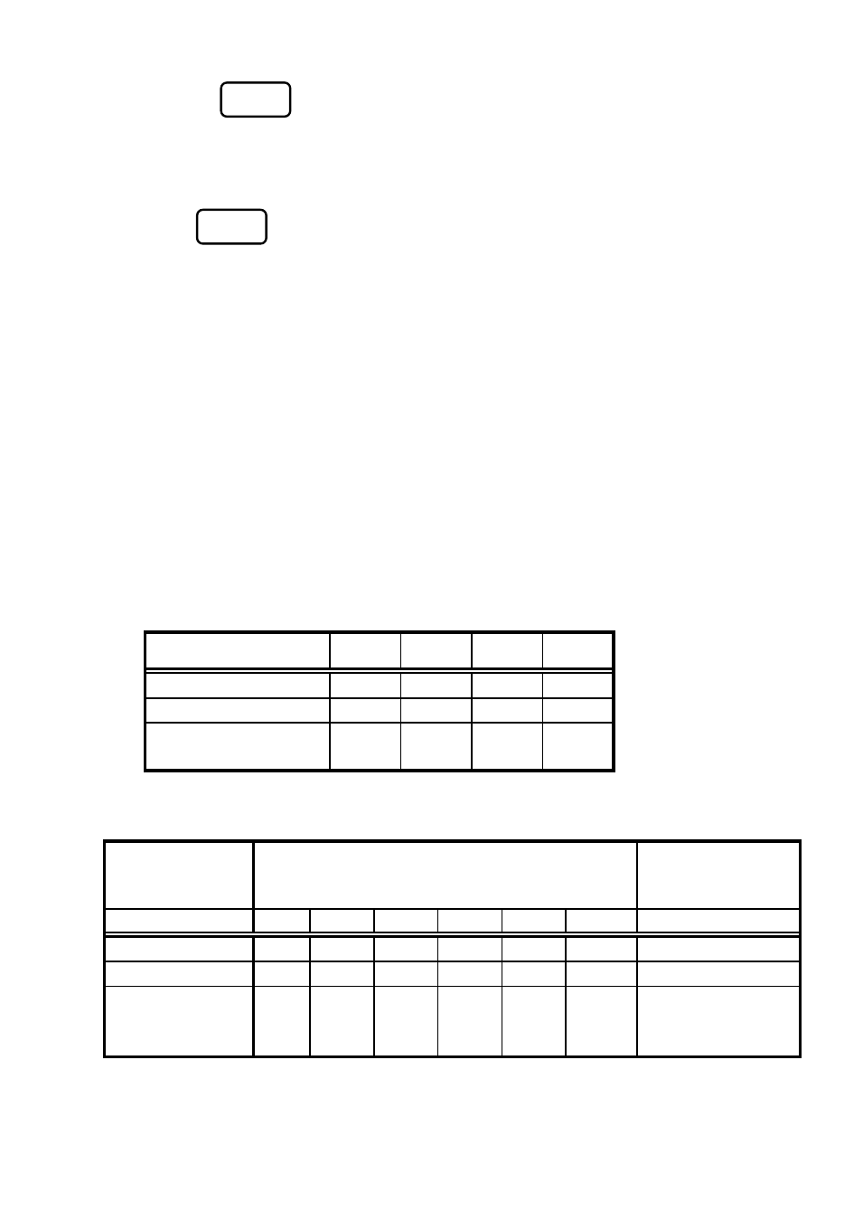
9.7 Reference Level Setting Range for Each Unit
Unit
dBm
dBμV
dBmV
dBV
Maximum
10
117
57
-3
Minimum
-40
67
7
-53
Minimum
(shifted spectrum data)
-60
47
-13
-73
“Available unit in measuring function”
Unit
dBμV/m (Electric field strength measurement)
dBμA/m
(Magnetic field strength
measurement)
Setting
M401
M402
M403
M404
M405
M406
CP-2S
Maximum
143
146
149
150
137
159
160 ~ 203
Minimum
93
96
99
100
87
109
110 ~ 153
Minimum
(shifted spectrum
data)
73
76
79
80
67
89
90 ~ 133
* When the reference level is set between “Minimum” and “Minimum (shifted spectrum data)”, the
spectrum of “Minimum” is shifted and displayed on the screen.
F3
F6