Alpha Technologies FXM350_Micro350 UPS User Manual
Page 30
017-241-B0 Rev B
28
Before starting, disconnect the Line power.
If stranded wires are used for connection at the input terminal block, ferrules or equiva-
lent crimping terminals must be used.
Separate the AC input power cables from the output power cables within the Alpha FXM
enclosure. Route them through separate conduit openings in the enclosure.
Separate the DC Battery cable from the AC Input and Output power cables. Route the
cable through its own opening.
WARNING!
5.1.2 Wiring the Micro350
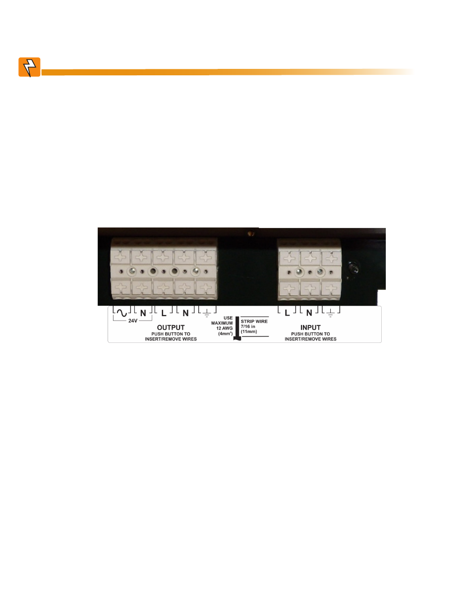
The AC power distribution terminal blocks in the Micro350 enclosure are located in the below the FXM350
(see Figure 16). Refer to Table S for detailed electrical specifications.
Figure 16 — AC Power distribution terminal blocks
OUTPUT
PUSH BUTTON TO
INSERT/REMOVE WIRES
INPUT
PUSH BUTTON TO
INSERT/REMOVE WIRES
L
N
STRIP WIRE
7/16 in
(11mm)
USE
MAXIMUM
12 AWG
2
(4mm )
L
24V
N
Have the following tools and materials on hand:
• Hammer for removing the knockouts
• Slot head screwdriver, 3/16 or smaller, to attach wires to the terminal blocks for the dry contacts / user
inputs on the front panel
• Slot head screwdriver, 1/4 or larger, for removing the knockouts
• DC voltmeter
• Battery terminal corrosion inhibitor such as NOCO Company’s NCP-2 or Sanchem Inc. No-Ox ID Grease
“A”
• Maximum of 12 AWG wire for wiring the input and output terminal blocks
• If used, 1/2" conduit connectors to fit the knockouts (7/8" diameter) and armored conduit to fit
• Optional battery heater mats