3 fxm350 front panel – Alpha Technologies FXM350_Micro350 UPS User Manual
Page 15
13
017-241-B0 Rev B
2.3 FXM350 Front Panel
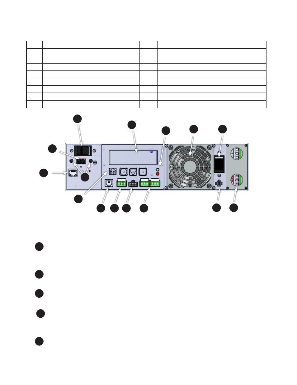
The following table and Figure 3 identify the main features of the FXM350 which are described in detail in the
following pages.
Item
Description
Item
Description
1
Battery breaker
8
Optically isolated user inputs
2
Battery connector
9
Additional user inputs and dry contacts connector
3
RJ45 communication module connector
10
Status and alarm LEDs
4
LCD control panel and menu navigation buttons
11
Configurable dry contacts, C1 and C2
5
USB communication connector
12
Replaceable fan assembly
6
Battery temperature sensor connector
13
AC input circuit breaker
7
Battery voltage test points
14
Battery heater mat connector
15
AC input/output connections
Figure 3 — FXM 350 front panel description
1
9
2
5
6
11
3
4
10
8
13
14
12
15
7
1
Battery breaker
This circuit breaker provides over-current protection and is used as an on/off switch for the battery power. It
must be switched on for proper Alpha FXM operation.
2
Battery connector
The battery connector connects the external batteries to the Alpha FXM.
3
RJ45 communication module connector
This RJ-45 connector is the Alpha FXM Ethernet connector.
4
LCD control panel and menu navigation buttons
The LCD control panel together with the cancel, scroll and select buttons are used to monitor and control the
Alpha FXM350.
5
USB communication connector
This USB communication connector provides a direct connection to the USB port of a standard computer
USB port (USB 2) for remote monitoring.