Optional accessory installation — voicelift system, Installation procedure, Vlp 102 pendant microphone – Extron Electronics PoleVault IP Systems PVS 305SA IP User Manual
Page 48: Vlr 102 receiver, Plug voicelift cable into pvs 305sa ip, Polevault ip systems • optional accessories 44
b
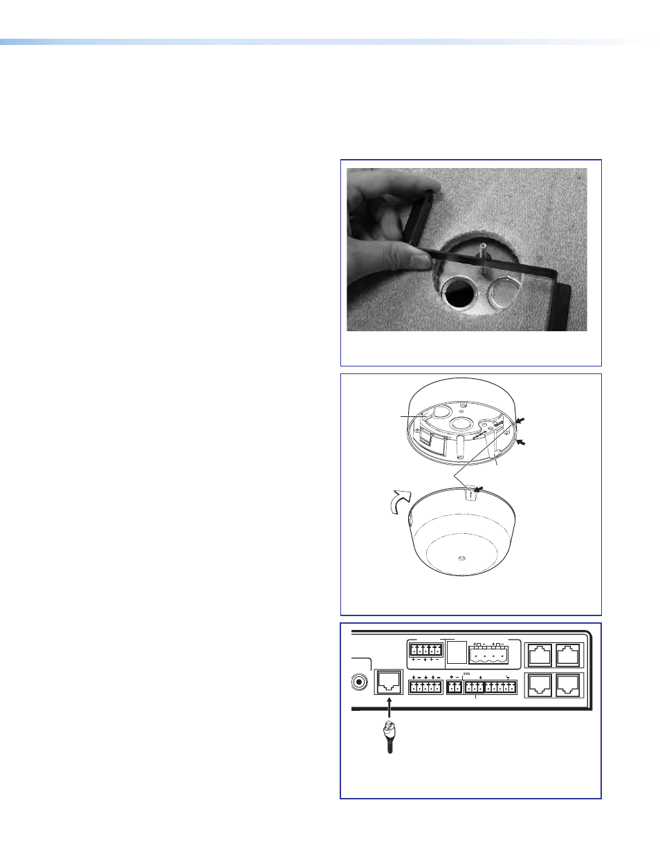
Attach the Z bracket to the ceiling tile
and the back plate.
g
Align the arrows on the housing rim and
the dome tab.
Arrow
Receiver
Dome
Twist to
Lock
Align Arrows
Arrow
Dot
Tab
Tab
i
Plug VoiceLift cable into PVS 305SA IP.
Optional Accessory Installation — VoiceLift System
The Extron VoiceLift system is an easy-to-use, low-power, voice amplification system that ensures the speaker’s
voice can be clearly heard at a comfortable level throughout the classroom. Speech is picked up by the pendant
microphone worn by the teacher and is transmitted via wireless from a base station receiver and the
PVS 305SA IP to the installed ceiling speakers.
For detailed installation information, see the
VoiceLift Installation Instructions, supplied
with the device.
VoiceLift System Included parts:
•
VLP 102 pendant microphone
•
VLR 102 Receiver
•
Wall charger
Installation Procedure
1. Determine the optimal receiver location and
mark and drill a 2.5 inch diameter hole in the
ceiling tile where it is to be installed.
2. Insert the ceiling bracket screw through the back
plate (attached to the housing) and the hole in the
ceiling tile and loosely attach the Z bracket.
3. Align the back plate knockout over the hole in the
ceiling tile and tighten the bracket screw to secure.
4. Replace the ceiling tile.
5. Pull the communication and power RJ-45 Ethernet
cable (and other secondary use cables) through
the receiver base and connect the Ethernet cable
to the Receiver Out port (the RJ-45 connector on
the left on the receiver base).
6. If desired, set the Tone and Mix DIP switches on
the receiver base.
7. Place the dome onto the housing, align the arrows
on the dome locking tab and on the housing rim.
Turn the dome until it locks in place (approximately
1/8 turn).
8. Pull the cables from the receiver to the
PVS 305SA IP switcher location, through the pipe
and down into the PMK 550.
9. Disconnect the power from the switcher, and plug
the included VoiceLift RJ-45 into the
PVS 305SA IP VoiceLift receiver port.
10. Replace power to the switcher. This also powers
the VoiceLift receiver.
L
R
L
R
L
R
AUX AUDIO
INPUT 5
LINE OUT
VOICELIFT
RECEIVER
PAGING
SENSOR
DO NOT
GROUND
OR SHORT
SPEAKER
OUTPUTS
1B RGB
1A RGB
2B RGB
2A RGB
3B RGB
/VIDEO
4B RGB
/VIDEO
3A RGB
4A RGB
I
N
P
U
T
S
RS-232 MLC/IR
2/4/8
Ohms
CLASS 2 WIRING
AMPLIFIED AUDIO OUT
VOL/MUTE
Tx Rx IR
12V
10V
50mA
POWER
RGB
VIDEO
OUTPUTS
CONTROL
N15779
12V
5A MAX
LAN 3
LAN 4
LAN 1
LAN 2
VoiceLift
Input
PoleVault IP Systems • Optional Accessories
44