Stage 2, Pvt cv d, Pvt rgb d ip plus – Extron Electronics PoleVault IP Systems PVS 305SA IP User Manual
Page 25: The pvt cv d is a 1-gang wallplate, The pvt rgb d ip plus is a 2-gang wallplate
COMPUTER IN
AUDIO
IN
OUT
MONITOR OUT
IR OUT
S G
Audio and Video
Output Port (at rear)
PVT CV D
AUDIO IN
L
R
VIDEO IN
IR OUT
S G
Decora
Faceplate
Mounting
Screws (2)
IR Output
IR Input
Connector
(at rear)
IR Input
Connector
(at rear)
Line Out
Audio
Connector
(at rear)
Audio and Video
Output Ports (2** at rear)
** Each RGB Wallplate needs
2 Output Cables, A and B.
Audio and
Video input
Connectors
RJ-45 LAN Pass-through
Connectors (2 at rear)
CAT5e
CAT5e
GS
GR
L
RGB A
OUT
RGB B
OUT
PVT RGB D IP Plus
IR Output
Audio and
Video input
Connectors
Line Out Audio
Output Port
Local Monitor
Output Port
CAT5e
CAT5e
RJ-45 LAN
Pass-through
Input
Connectors
FRONT
REAR
REAR
FRONT
12
3
4
ON
5
5-pole EDID
DIP switch
(at rear)
EDID Learn
Button
EDID Learn
Status LED
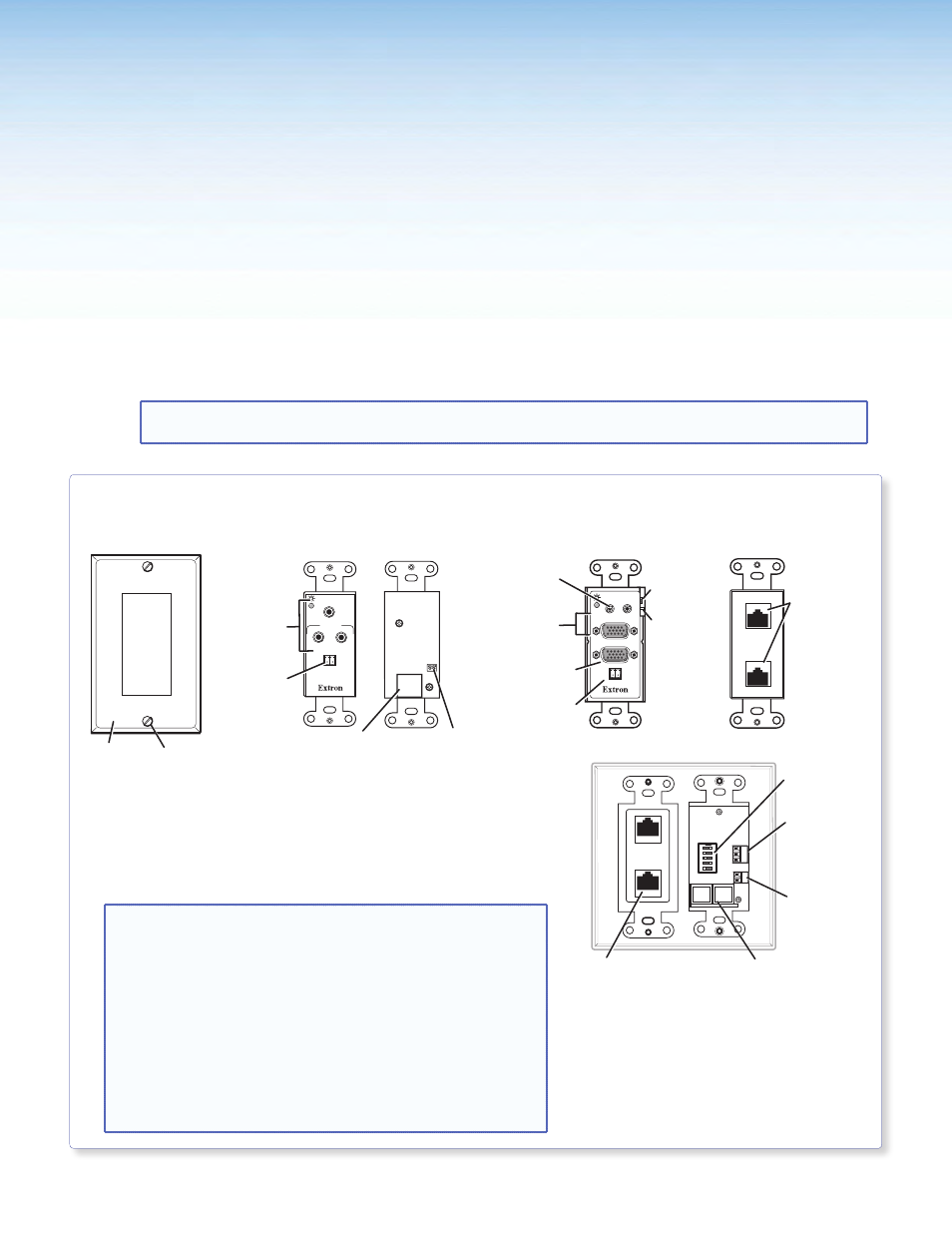
Stage 2:
Mounting the PVT
Wallplates and the
MediaLink Controller
Stage 2 Involves Installing and Cabling the Devices Shown Below.
NOTE: The installation must conform to national and local electrical codes and UL requirements. See the
device user guide for details.
PVT CV D and PVT RGB D IP Plus AV Source Input Wallplates
•
Where it goes: Installs in a wall near input source location.
•
What it does: Transmits an input source’s composite or RGB
video signal and audio signals to the switcher.
In addition the PVT RGB D IP Plus allows pass-through Ethernet
connection.
NOTES:
•
The PVT CV D is a 1-gang wallplate.
•
The PVT RGB D IP Plus is a 2-gang wallplate.
•
Both the PVT RGB D IP Plus and the optional
PVT RGB D (EDID) incorporate EDID Minder. This allows
the transmitter to communicate the appropriate EDID
information to the source, ensuring correct video output
resolution.
Before fully installing the PVT RGB D IP Plus wallplate,
see
on page 42 for setup and operating
details.
PoleVault IP Systems • Installation — Stage 2 (Wallplates and MLC)
21