Connect to the lan using a cat 5 cable, Terminal rs-232 cable color pin, Terminal ir/rs-232 cable color ir cable color – Extron Electronics PoleVault IP Systems PVS 305SA IP User Manual
Page 31
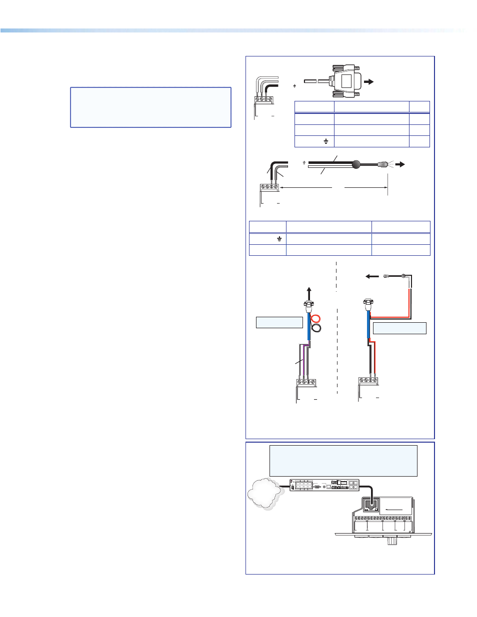
b. Connect the IR/RS-232 projector
communication cable as shown for either
RS-232 or IR projector control
NOTE: Some projectors require NULL
connection wiring, which inverts the Tx
and Rx connections. See the projector
guide for details.
c. Connect a network cable (CAT 5, 5e, or 6
straight through) from the PVS 305SA IP to the
RJ-45 LAN jack on the MLC.
The switcher acts as a 4-port Ethernet switch,
when connected to the LAN via the RJ-45
pass-through ports on the rear of the
PVT RGB D IP Plus wallplates .
á
Connect the MLC to the projector with an
RS-232 cable or IR emitter cable, as appropriate.
1
2
3
GROUND
+12V OU
T
CM
GROUND
IR OU
T
G
ROUND
SC
P
GROUND
Tx
Rx
DISPLAY
RS-232/IR
A B C D E
COMM LINK
LAN
PRESS TAB WITH
TWEEKER TO REMOVE
A B
MLS
RS-232
POWER
12V
DIGITAL
I/O
IR IN
Tx
GROUND
Rx
+12V IN
MLC 104 IP Plus Right Side Panel
TCP/IP
Network
CAT 5, 5e or 6 Cable
PVS 305SA IP
L
R
L
R
L
R
AUX AUDIO
INPUT 5
LINE OUT
VOICELIFT
RECEIVER
PAGING
SENSOR
DO NOT
GROUND
OR SHORT
SPEAKER
OUTPUTS
1B RGB
1A RGB
2B RGB
2A RGB
3B RGB
/VIDEO
4B RGB
/VIDEO
3A RGB
4A RGB
I
N
P
U
T
S
RS-232 MLC/IR
2/4/8
Ohms
CLASS 2 WIRING
AMPLIFIED AUDIO OUT
VOL/MUTE
Tx Rx IR
12V
10V
50mA
POWER
RGB
VIDEO
OUTPUTS
CONTROL
N15779
12V
5A MAX
LAN 3
LAN 4
LAN 1
LAN 2
NOTE: Connect to the PVS 305SA IP Ethernet ports as follows:
1. TCP/IP network
2. MLC controller
3. PVT RGB D IP Plus RJ-45 pass-through
4. PVT RGB D IP Plus RJ-45 pass-through
ó
Connect to the LAN using a CAT 5 cable.
MLC 104 IP Plus
Right Side Panel
Ground ( )
Receive (Rx)
Transmit (Tx)
GR
O
UND
IR OU
T
Tx
Rx
DISPLAY
RS-232/IR
RS-232 to projector
RS-232 connection
Terminal RS-232 Cable color Pin
Tx
White
2
Rx
Violet
3
Ground
Shield
5
Terminal IR/RS-232 Cable color IR Cable color
Ground
Black
Black
IR Signal
Red
White/Black
Red
Black
Projector
MLC IR/RS-232
Comm Cable
IR Emitter
Connecting IR Cable
White
(or striped)
Black
Red
Black
9-Pin Female
White
Violet
Shield
MLC 104 IP Plus
Connecting RS-232 Cable
Projector
GROUND
IR OU
T
Tx
Rx
DISPLAY
RS-232/IR
GROUND
IR OU
T
Tx
Rx
DISPLAY
RS-232/IR
NOTE: Red and black
not used.
NOTE: White, violet, and
shield not used.
MLC 104 IP Plus
Right Side Panel
To projector
Ground ( )
IR Signal
Unidirectional IR Output
via White Striped Wire
IR Emitter
100'
(30.5 m)
GR
O
UND
IR OU
T
Tx
Rx
DISPLAY
RS-232/IR
IR connection
Black
Black
Red
PoleVault IP Systems • Installation — Stage 2 (Wallplates and MLC)
27