— terminate the speaker cable for the pvs switcher – Extron Electronics PoleVault IP Systems PVS 305SA IP User Manual
Page 36
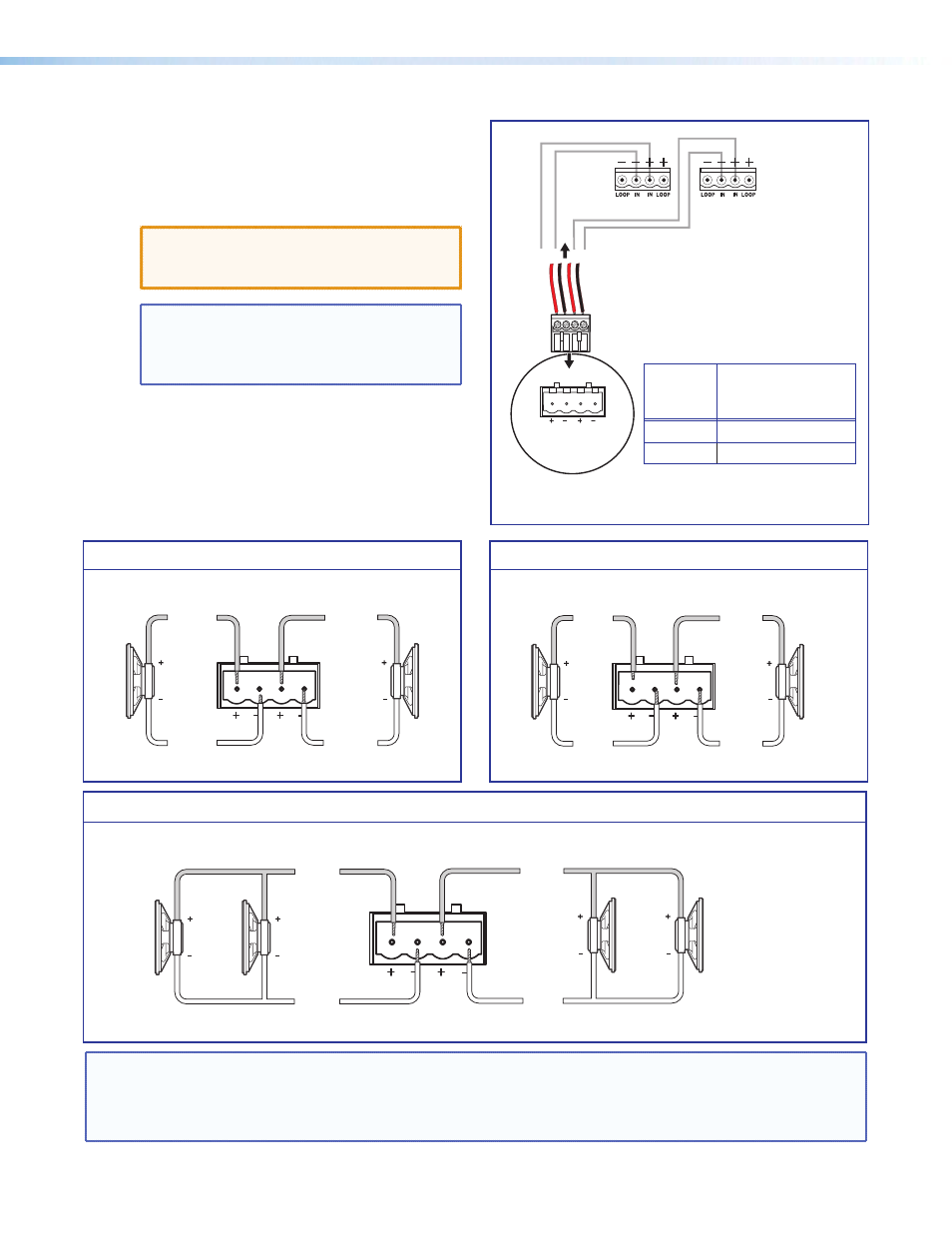
3. — Terminate the Speaker Cable for the PVS
Switcher
a. To terminate the cable, strip the end of the
cable 0.2 inch (5 mm) and secure the wires into
the supplied 4-pole captive screw connector.
ATTENTION: DO NOT short the speaker
wires together as it may damage the
switcher.
NOTE: The correct speaker impedance load-
ing must be observed when setting up
a speaker system. See figures below for
examples.
Stereo or dual mono output using parallel speaker wiring
Dual mono output
8 Ohm Load
L
R
8 Ohms
AMPLIFIED OUTPUTS
Mono –
Mono +
Mono –
Mono +
4 Ohm Total Load
4 Ohm Total Load
Two 8 ohm speakers
wired in parallel
equal a 4 ohm load.
L
R
2/4/8 Ohms
AMPLIFIED OUTPUTS
Mono –
or
Stereo R-
8
ohms
8
ohms
Mono +
or
Stereo R+
Mono –
or
Stereo L-
Mono +
or
Stereo L+
8
ohms
8
ohms
8 Ohm Load
Stereo R–
Stereo R+
Stereo L–
L
R
8 Ohms
AMPLIFIED OUTPUTS
Stereo L+
Stereo output
NOTE: By default, the amplifier is set for dual mono output. Use the software or Extron Special Instruction Set
(SIS) commands to change the setting to stereo if desired. For full details, see the PVS 305SA User Guide,
. The commands given in that manual are also applicable to the
PVS 305SA IP switcher.
Ñ
Wire the captive screw connector.
PVS Switcher
Rear Panel
Speaker 1
Speaker 2
L
R
4/8
Ohms
AMPLIFIED OUTPUTS
4-pole Captive
Screw Connector
Audio output
to speakers
Speaker
Wire
color
To PVS 305SA IP
terminal (Left and
Right)
Red
Positive (+)
Black
Negative (-)
PoleVault IP Systems • Installation — Stage 3 (Speakers)
32