Mls 104 ip plus medialink controller, Right side, Rear view – Extron Electronics PoleVault IP Systems PVS 305SA IP User Manual
Page 26: What it does, Pvt transmitter installation, Provides remote control of switcher and projector, Mounting screws (4), Location of mac address, Captive screw connectors for
CONFIG
DISPLAY
VOLUME
MLC 104 IP PLUS
ON
VCR
DVD
PC
OFF
1
2
3
4
Mounting
screws (4)
1
2
3
GROUND
+12V OUT
CM
GROUND
IR OUT
GROUND
SCP
GROUND
Tx
Rx
DISPLA
Y
RS-232/IR
A B C D E
COMM LINK
LAN
PRESS
TAB
WITH
TWEEKER
TO
REM
OV
E
A B
MLS
RS-232
PO
WER
12V
DIGIT
AL
I/O
IR IN
Tx
GROUND
Rx
+12V IN
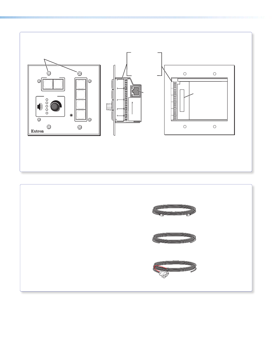
Right Side
Ethernet
port
Display/RS-232/IR
Comm. Link
Digital I/O,
MLS/RS-232
Power
RUN
100
00-05-A6-01-6B-F5
Location of
MAC address
Rear View
Captive screw connectors for:
MLS 104 IP Plus MediaLink Controller
•
Where it goes: Installs in a wall at a location convenient to user.
•
What it does:
Provides remote control of switcher and projector.
Cabling for the Wallplates and MediaLink Controller
PVT transmitter installation
•
CAT 5 T568A signal transmission cables
(connects PVT input wallplates to PVS 305SA IP switcher)
MLC 104 IP Plus installation
•
MLC power and RS-232 control cable
(connects the MLC controller to the MLC/Power
control port on the PVS 305SA IP switcher)
•
IR/RS-232 communications cable control cable
(connects the MLC controller to the projector via
RS-232 or to an IR emitter)
•
LAN network cables (not supplied - connects the MLC
controller to LAN)
MLC, PW/RS-232/VC, 50 ft
26-626-50
IR SERIAL COMM, 50 ft
26-621-50
CAT 5 Patch, 50 ft
26-637-50
PoleVault IP Systems • Installation — Stage 2 (Wallplates and MLC)
22