Alarm, Fiber optic connection, Alarm fiber optic connection – Extron Electronics PowerCage FOX Tx_Rx AV User Guide User Manual
Page 16
Alarm
e
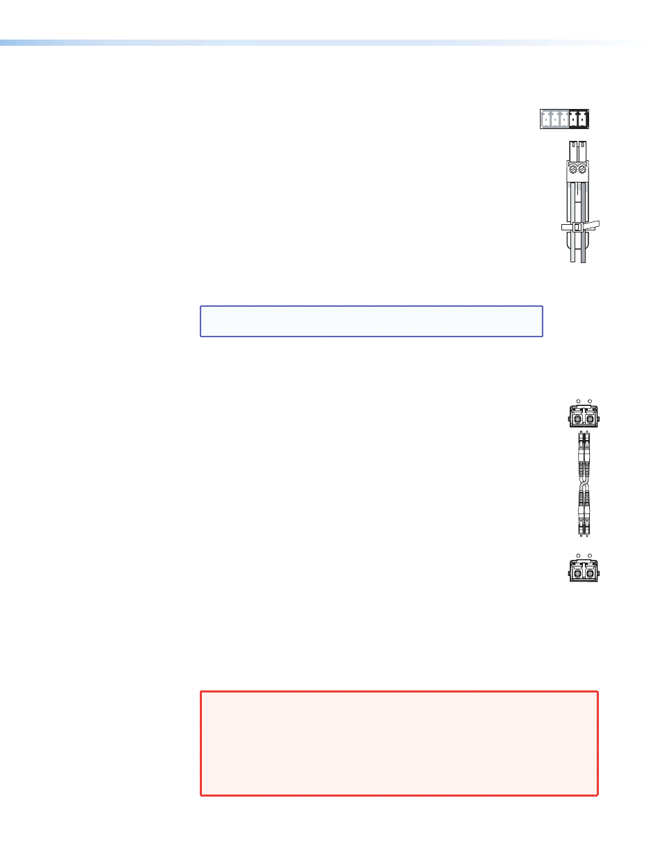
Alarm connector — When an alarm is connected to it, a warning
signal is issued through the two rightmost poles of the 5-pole RS-232
Remote/Alarm captive screw connector when light signals have been
disconnected, lost, or broken.
The alarm pins, labeled 1 and 2, (see the illustration at right) of this
contact closure port act are shorted together when the signal is lost.
The port does not produce any discrete on and off voltage signals but
acts as an internal relay that either connects or disconnects an external
alarm circuit.
z
For the PowerCage FOX AV transmitter, the alarm state is activated
when link 2 is absent.
z
For the PowerCage FOX AV receiver, the alarm state is activated
when link 1 is absent.
z
When power is lost, the alarm state is activated for both units.
NOTE: Strip the wires using the same methods shown for the
Fiber Optic Connection
f
Optical connector — An LC duplex SFP connector links the transmitter and
receiver. An LED above each port lights when the port receives a signal.
z
The optical Rx port on the receiver unit lights when a signal from fiber
link 1 reaches the receiver.
z
The optical Rx port on the transmitter unit lights when a signal from
link 2 reaches the transmitter.
The transmitter and receiver units of the PowerCage FOX Tx/Rx AV are
connected by an LC duplex SFP connector. Fiber optic link 1 connects the Tx
port of the transmitter and the Rx port of the receiver. It carries video, audio,
and data output from the transmitter to the receiver.
Fiber optic link 2 connects the Tx port of the receiver with the Rx port of the
transmitter. It carries only the responses to RS-232 commands and is not
required for transmitting video and audio signals.
However, if link 2 is not enabled, the ability to configure the system through
SIS commands is limited by the lack of communication from the receiver to the
transmitter. All commands issued through the transmitter are valid but
responses to status queries may return invalid data.
Signals can be transmitted 2 km (6561 feet) over multimode (MM) fiber and
30 km (18 miles) over singlemode fiber (see the “
” specification
in the “Reference Information” section). A MM transmitter must always be connected
to a MM receiver and a SM transmitter can only be connected to a SM receiver.
WARNINGS: The PowerCage FOX Tx/Rx AV outputs continuous invisible light
(Class 1 rated), which may be harmful and dangerous to the eyes;
use the product with caution.
•
Do not look into the rear panel fiber optic cable connectors or
into the fiber optic cables themselves.
•
Plug the attached dust caps into the optical transceivers when the
fiber optic cable is unplugged.
1 2
ALARM
REMOTE
RS-232
Rx
Tx
OPTICAL
Rx
Tx
OPTICAL
PowerCage FOX Tx/Rx AV • Installation and Operation
10