Included parts, Cables, Mla‑vc10 functional block diagram – Extron Electronics MLA-VC10 User Manual
Page 49: Mla-vc10 functional block diagram, Mla-vc10 • reference information
MLA-VC10 • Reference Information
A-3
Included Parts
These items are included in each order for an MLA-VC10:
Included parts
Replacement
part number
MLA-VC10
60-502-01
3.8 mm, 2-pole captive screw connector
10-319-15
3.5 mm, 5-pole captive screw connector
10-319-10
User’s manual
Cables
Plenum Comm-link cable
Part number
CTLP/500: 500' (150 m)
22-119-02
CTLP/1000: 1000' (300 m)
22-119-03
CTLP/400: 400' (120 m)
26-461-04
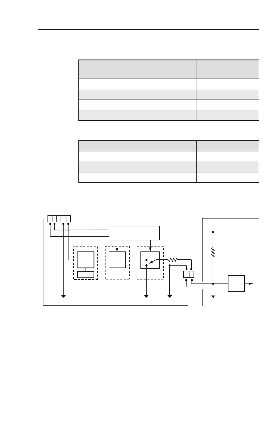
MLA-VC10 Functional Block Diagram
MLA-VC10
Control
Voltage
High Z
Amp/Mixer
+V
Microcontroller
Relay
DIP Sw.
Digital
Pot.
Digital
Pot.
Low Z
RS-232/MLC Control
Sets Max Voltage
Tx Rx Gnd+12V
DC Voltage Controller
Power Up Amp
Protection
MLA-VC10 Block Diagram.eps
- Amp/Mixer must support remote volume capabilities.
- Output impedance of MLA-VC10 is lower than the input impedance of the Amp/ Mixer.
- DIP switches set maximum control voltage (10VDC max.).
- Relay shorts to ground when power is removed and for 5 seconds after power up.
- AVTrac Corner Cut Solution (2 pages)
- AVTrac Demonstration Kit (2 pages)
- AVTRac End Ramp and Cable Pass-Through Kits (1 page)
- AVTrac Extension Kit (15 pages)
- 1U and 2U Rack Plate (1 page)
- Under-Desk Mounting Bracket (1 page)
- AAP Wiring Guide 68-1054-01 (1 page)
- AAP Wiring Guide 68-1052-01 (1 page)
- AAP Wiring Guide (XLR connectors) (1 page)
- AAP 314 (1 page)
- AAP 301 (1 page)
- AAP Wiring Guide 68-1055-01 (1 page)
- AAP Wiring Guide 68-1058-01 (1 page)
- AAP Wiring Guide 68-1059-01 (1 page)
- AAP-MAAP Rev. A (1 page)
- AAP-MAAP Rev. D (1 page)
- MD Floor Box AAP Bracket Kit AAP 100 MD (1 page)
- AC 100 Power Module Series (1 page)
- AAP 103 Extron Ackerman AKM UK Faceplate Kit (1 page)
- ACMP 100 (2 pages)
- Active Audio AAP (1 page)
- AKM UK Series (4 pages)
- Audio AAP Wiring Guide (1 page)
- Audio Connector Rev. A (2 pages)
- Audio Connector Rev. G (1 page)
- AVTrac Extra Channel Kit (2 pages)
- AVTrac Raceway Transition (2 pages)
- AVTrac Retrofit Transition Adapter (2 pages)
- AVTrac Trim Ring-Rough-in Adapter (2 pages)
- AVTrac Above Floor (1 page)
- BB 1 (2 pages)
- BB 1000M (2 pages)
- BB 700M (2 pages)
- BB 710M (2 pages)
- Blank Rack Panel (1 page)
- BNC to 15-Pin HD (1 page)
- BNC-5 RC Termination (1 page)
- Cable Cubby 1200 (6 pages)
- Cable Cubby 200 (18 pages)
- Cable Cubby 300C (27 pages)
- Cable Cubby 500 (6 pages)
- Flexible Conduit Kit (2 pages)
- Cable Cubby Lid and Trim Ring Replacement Kit (for 300C, 300S, 600, 800) (1 page)
- Cable Cubby Setup Guide (4 pages)
- Cable Cubby Single Space AAP Bracket Kit (1 page)