Front and rear panel features, Installation and setup – Extron Electronics MLA-VC10 User Manual
Page 14
MLA-VC10 • Installation and Setup
Installation and Setup
2-2
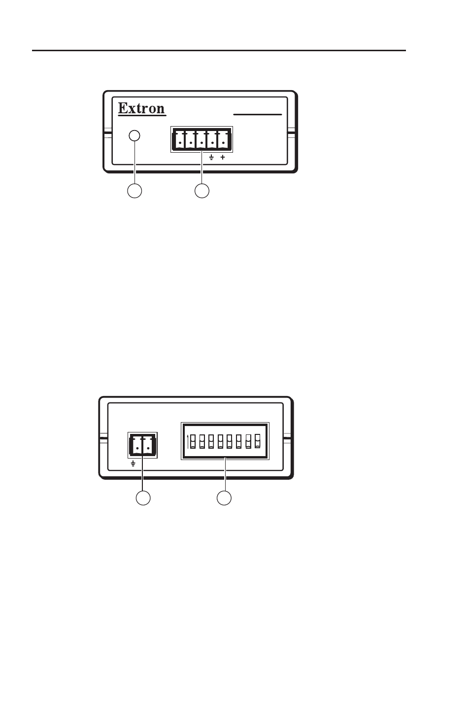
Front and Rear Panel Features
Figure 2-1 — MLA-VC10 front panel
a
Power/Status indicator LED — This LED lights steadily while
the MLA-VC10 receives power, and blinks three times when the
MLA-VC10 receives valid RS-232 volume setting commands.
b
MLC/RS-232 Power connector — This 5-pole, 3.5 mm captive
screw connector is for transmitting and receiving RS-232 signals
and for power and ground connections. Connect cables to this
port for:
a MediaLink Controller (MLC) and the MLC's 12 VDC power
supply, or
an external 12 VDC power supply and a third party RS-232
control device
Figure 2-2 — MLA-VC10 rear panel
c
Amp/Mixer Control connector — Connect a cable between the
amplifier's or mixer's remote control port and this 2-pole 3.5 mm
captive screw connector to provide a ground and control voltage
for regulating the audio volume.
d
Configuration DIP switches — Set these eight switches to
configure the MLA-VC10 for the control voltage required by the
amplifier or mixer. See "DIP switches" on page 3-11.
•
•
MLA-VC10
POWER/
STATUS
A B
MLC/RS-232
POWER
1
2
CTRL
AMP/MIXER
CONTROL
1 2 3 4 5 6
ON
7 8
CONFIGURATION
3
4